• Please review our updated Terms and Rules here

Tandy 1000EX PSU issue

tgotr

Member
Joined
Dec 5, 2020
Messages
16
Location
Southern, Michigan
Ok, my Tandy 1000 EX PSU blew up. I took the computer apart to clean it thoroughly. I washed everything in warm water, except for the PSU and let the motherboard dry for a week in a dry environment. Something I've done 100 billion times it seems with no issue on other machines.

I go to reassemble the system and test it. The PSU made a wine and the fuse blew. The computer didn't turn on. I got the correct voltages out of the PSU when the fuse wasn't popping. I replaced the fuse a few more times, kept blowing. Eventually I did a stupid and jumped the fuse (It was only a temporary thing so I could troubleshoot it) which caused a couple regulators to pop.

Would a PicoPSU be enough to power a 1000 EX, that is if the Motherboard isn't fried.

On the bright side, the computer looks phenomenal.
 
It should be pretty easy to run the Tandy motherboard from any kind of ATX PSU just by jumpering the power-on signal to ground through a switch, but the fact that it wasn't doing this before you washed the motherboard makes it sound a like you're barking up the wrong tree here.
 
It should be pretty easy to run the Tandy motherboard from any kind of ATX PSU just by jumpering the power-on signal to ground through a switch, but the fact that it wasn't doing this before you washed the motherboard makes it sound a like you're barking up the wrong tree here.

I just figured out why the mobo wasn't starting.

I got rid of the RF shielding paper because it was growing mold and it was shorting. I hope the board isn't destroyed.
 
You can look for obvious scorch marks on the motherboard, if you're lucky the short you created was directly between some beefy ground and voltage supply lines and the power supply took all the damage itself, but, yeah, for future reference it's generally not a good idea to short around a fuse that keeps popping, there *is* probably a reason.
 
Yeah..... In my younger days I destroyed the main transformer (irreplaceable) in a vintage Sunn Sceptre all-tube guitar amp head like that. ;_;

Fuses blow for a reason. :(
 
I wired up an ATX PSU, and the computer POSTed, just didn't hook up a screen, but the CPU did cut the sound chip off. So need to find a way to isolate the board from the metal grounding plate. Was thinking plastic washers if they don't affect the height too much.
 
Yeah..... In my younger days I destroyed the main transformer (irreplaceable) in a vintage Sunn Sceptre all-tube guitar amp head like that. ;_;

Fuses blow for a reason. :(

I figure the coils failed due to the short. That's where the sparks came from and the passives around the coils are fine. I have some plans drawn up to use a PicoPSU as an EX/HX PSU as a drop in replacement instead of modifying the harness.
 
That's a really great idea!

I have a design coming from OSHpark. It's not mountable, just to see if things work. It's a Revision .05 to be fair. To see if I need to put in a linear regulator for the -12V line to make it more powerful (doubtful since the Tandy board says it only does 0.01 Amps), see if my idea of laying the picoPSU flat will work. Also, I want to see where the right place would be to extend the board out to mount on on the existing mounting points in the EX case...are the HX mounting points identical? I don't have one to see.
 
I have a design coming from OSHpark. It's not mountable, just to see if things work. It's a Revision .05 to be fair. To see if I need to put in a linear regulator for the -12V line to make it more powerful (doubtful since the Tandy board says it only does 0.01 Amps), see if my idea of laying the picoPSU flat will work. Also, I want to see where the right place would be to extend the board out to mount on on the existing mounting points in the EX case...are the HX mounting points identical? I don't have one to see.

Yes, at least mine are.

There are some different case revisions on the HX, though. I think the only change is the volume knob, but there may be others.
 
I have a design coming from OSHpark. It's not mountable, just to see if things work. It's a Revision .05 to be fair. To see if I need to put in a linear regulator for the -12V line to make it more powerful (doubtful since the Tandy board says it only does 0.01 Amps)

Re: -12v, don’t worry about it. So far as I’m aware the only thing it’s ever used for in a Tandy 1000 is to supply the negative bipolar voltage for a serial port (if present). An unexpanded EX wouldn’t need it at all.
 
Re: -12v, don’t worry about it. So far as I’m aware the only thing it’s ever used for in a Tandy 1000 is to supply the negative bipolar voltage for a serial port (if present). An unexpanded EX wouldn’t need it at all.

I was thinking the same thing. I couldn't find anywhere on the board where the -12 rail went. I didn't look at a schematic though.
 
So far as I know there’s going to be just one trace to the expansion port. (I’ve designed and built my own serial expansion cards for the EX and HX so I do know for a fact it’s there, but I can’t think of anywhere else that might use it.)

Also, the only non-serial uses for +12v on those machines is drive motors and fans. There isn’t any of the nasty multi-voltage logic or RAM you’ll run into on older machines. (Example: 4116 RAM chips.)
 
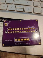
IMG-20210106-150625-1.jpg

Here is the basic board. I made a mistake, had the board fabricated with the wrong size header.

The board can be mounted through the corner screw hole, and users can install stand-offs if they like.

The ATX connector is intended to be a 90 degree connector so the PicoPSU lays flat This is to alleviate any clearance issues, and to use the rear fan to pull heat off it. If I do a 2nd version, I'll put in a fan header so a new fan can be used,

The main header can be populated with any male headers with a 3.98 pin spacing. You can also just populate the left six holes if you are using the Pico PSU's harness to power the floppy drive, useful if you have a Gotek, a 3 1/2 inch floppy drive, or something that uses the floppy power connector.

You can use the original switch with this by soldering female connectors to it and connecting them to the appropriate spots on the board.
 
Any update on this? Can the corrected version of the board be ordered somewhere? Or is there a ready-to-go Gerber file that can be used to have such a PCB etched somewhere?

I recently acquired a Tandy 1000 EX myself. It takes 120V AC power, but I'm in Europe. I guess I could use a transformer, but a solution like yours would be more elegant. (Not to mention less noisy and more power-efficient.)

Thanks for your efforts in this! :)

EDIT: I found your GitHub page for this project. I'll take a look there. :)
 
Last edited:
Back
Top