• Please review our updated Terms and Rules here
  • From now on we will require that a prefix is set for any items in the sales area. We have created regions and locations for this. We also require that you select a delivery option before posting your listing. This will hopefully help us streamline the things that get listed for sales here and help local people better advertise their items, especially for local only sales. New sales rules are also coming, so stay tuned.

Aluminum, Zinc, Brass casting?

Chuck(G)

25k Member
Joined
Jan 11, 2007
Messages
44,526
Location
Pacific Northwest, USA
I have a rather simple part about 1" thick and 2" in diameter that's glass-filled ABS. It's going to brittle-land.

I'd like to reproduce it in metal. I can probably do this in my shop from bits of brass stock, but I'm wondering if anyone has the facilities to duplicate the part in zinc/pot metal, or better, brass.

Please don't suggest 3D printing--this part takes a considerable amount of force and needs to be rigid and dimensionally stable.

Thanks for reading...
 
If it can be made by turning and milling, I can do it (if I can manage to find time). If it needs to be cast, I can probably make a mold. But as far as actually casting, I'm not really tooled up for that at the present. My forge is out of service and I'm not doing anything about that any time soon. I don't even have an oxy-fuel torch right now.
 
I'll see if I can pry it loose in the next week or so.

I can fab one out of brass stock, but would rather have it cast--should be easier. I'd like to get two. It's got to non-magnetic, so steel is out.

I'll also check with a local sculptor who works in bronze.
 
Quantity two, nonmagnetic. I'm guessing - tape drive hub?
As already mentioned, a photo would be good. Sometimes it's suitable to silver solder things together rather then hog it out of a solid block.
I had a bronze casting done for me at a railway workshop foundry, do you have a foundry nearby.
About 3D printing not being suitable - there's an interesting video on Youtube where an outboard motor propeller is printed in a few different materials and then tested on a harbour runabout. The polycarbonate and wood/PLA prints turned out to be the strongest, with a carbon fibre version surprisingly failing early in their tests.
 
And the specific dimensions aren't critical? I can't see how casting is favored as a pattern or die is needed. It's not going to be die cast, short of spending 10k$+, and sand casting requires removal of gritty texture. Back to machining. There's investment casting, which you might be able to get by with, but a vulcanized rubber mold would be necessary. Perhaps you could repo it in an open investment mold, like cuttlefish casting. But if this thing is going to spin it's going to have to be balanced. All this could be done in a rudimentary shop, I'm not volunteering. But in the end you'll probably find the wisest choice is to have duplicates machined. Farming it out won't be chump change for any method.
 
Yup--not the whole hub, but just the quick-release lever. You've probably seen my post on cctalk. Right now, I've simply swapped the release levers between the supply and takeup reels, but I know that this is just a temporary measure; sooner or later the other lever will fail.

Were I do fab one myself, I'd silver-solder the parts together--that's a no-brainer.

The problem with 3D printing is that the original has a fairly high glass fiber content--significant flexibility would kill it. On my other tape equipment, the hubs are die-cast, which makes a lot of sense. Clearly some HP engineer wasn't thinking--or perhaps just cutting corners.
 
There will probably be a need for more of these.

I'm about to dig into my 7970 drives to try duplicating what you've done.
 
The lever part... I have a workable solution to repairing levers and brackets that works extremely well. A few years ago I had the foldout front panel / feeder tray break on my HP Laserjet 4 break at one of the arm pivots. This bit is moulded ABS as part of the same panel. It's under a comparitvely large amount of stress (for its size). First I tried the liquid solvent I use for building scale models, without much confidence it would hold up. I was right, it broke pretty much straight away.
Then I glued it back and this time drilled two small 1/16" holes lengthwise through it and force-fitted two pieces of 1/16" carbon fibre rod, with epoxy. Worked fantastic.

I have also repaired other high-stress items with carbon fibre rod, for instance an GRP R/C vintage offroad buggy chassis that had cracked almost right through, near the steering arm recesses where it was thinnest. This time I could not drill and fit the rods internally so I drilled a series of 0.8mm holes along the sides where the rods would be fitted and then stiched and bound the rods in place with Kevlar thread, superglued at each loop then finished with epoxy. I have run this buggy a lot offroad since then, still perfectly fine.

Carbon fibre is at your local hobby shop, Kevlar thread from eBay (a cotton reel spool will last you years) butI bought my first spool of it twenty years ago at a fishing tackle shop where it was sold for putting the metal rings on fishing rods (apparently people like building their own custom ones). Both wonder materials and I can't recommend them enough.
 
Last edited:
The lever part isn't where the cracks (and stress) occurs. The thing is essentially a cam arrangement, pivoting on a rod extending through the cams. The weak point in the design is in the cam around the rod. You can see the part (3) here:


You can see how it operates--basically the lever cam presses against the main body of the release assembly, which then presses against the annular aluminum plate that squeezes a fat rubber doughnut, which expands to hold onto the reel hub. The screw assembly (7,8,9) prevents the release body from turning on the adjustment screw(5). There's a small setscrew (6) to hold the rod in place.
 
Last edited:
Thanks for the diagram Chuck. It looks even simpler than I imagined. I'd probably use the Kevlar alone if I were doing it, drill the holes right through the front of the tab, bind, superglue and epoxy. I've repaired a cracked 4" reflector telescope mounting that way, and have a 10" reflector telescope equatorial cast aluminium motor drive mount, also cracked, on my "gunnadoo" list using same. Wish I was closer, I'd give it a go.
 
Clearly some HP engineer wasn't thinking--or perhaps just cutting corners.

Or the 'plastic' was defective or wrong for the purpose.

I just tried all of them on my 7970B's and E, and the top one snapped off of the E
The material seems to be pretty brittle. I'm trying to glue it with some DAP Rapidfuse to see what happens

They should have put stress ridges perpendicular to the pin
 
My other thought was to discard the plastic (2 and 3) entirely and substitute a knob attached to a nice big annular metal ring that would bear directly on the rubber doughnut assembly. The adjustment screw 5 would serve the clamping function. Spin the knob right to mount; left to dismount. I've seen similar setups on other drives and quite possibly on old 1" videotape recorders.

They should have put stress ridges perpendicular to the pin
.

Instead, they put holes in the cam. Go figure. The glass content is pretty high, so I don't know if the DAP treatment will work. I've tried industrial cyanoacrylate adhesive, but it didn't hold past the first few operations.
 
So everything is intact except for part #3?

If that's the part you need, I wouldn't bother casting unless you needed a hundred. I would machine it directly from flat stock, brass or aluminium.
 
Agree with the machining from flat bar stock, milling them from a piece of Dural or 6061 aluminium would be perfect.

If the plastic was wrong for the purpose, then there might have been reports from the field at the time they were in operation, and engineering changes made. However those drives are now, what, 40 years old and with sunlight, active use and so on, they can develop microscopc fractures.
Although I love machining mild steel, dural and other metals, plastics are beatiful - I adore working with them. Their properties are perfectly consistent in cutting, machining, welding, sanding, painting, no grain (unless designed) and a host of other useful things. Give them a try, Chuck!
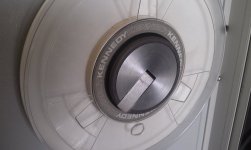
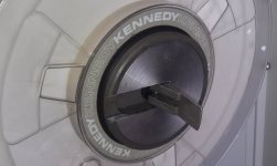
I just had a superficial look at my Kennedy 9000 drives and they have the same type of cam mechanism but the levers are about 7/8" wide and are cast from metal, as you can see below. These are only a few years younger then your 7970 drive, perhaps they learned something.
IMAG7216.jpgIMAG7217.jpg
 
I understand about the plastic degradation. I'm getting pretty brittle in my old age...

The tape hub levers on my Fuji 9-track drive as well as on my tape cleaner are metal also.

I figure this was nothing more than HP cutting a corner or two. That hub assembly on your Kennedy looks to be nicely machined--which could not have been very cheap.

This 7970 is used for reading 7-track and 9-track NRZI tapes, so it's not easily replaceable.
 
Last edited:
If you can run a vernier or digital caliper over it (Imperial or metric) I ought to be able to generate an STL for you that you can then email to a CNC fab shop and get quotes on having a few zapped out of aluminium bar stock.
 
If you trust me and USPS enough to send me the original part and bar stock, I'd make one or two for no cost and send them back. I'd need about two months; obviously it doesn't take that long, but I'd need that much time to be sure to get it done due to work schedules.

I'd not have time to make a proper part print nor IGES model, but you could have the sketches I'd likely have to make.
 
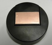
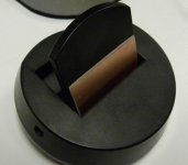
try double sided pcb material and rapidfuse
the bond was pretty solid just putting the two pieces together and letting it sit overnight
I'm waiting for the pcb to bond before I try it
hub1.jpghub2.jpg
 
Back
Top