• Please review our updated Terms and Rules here

IBM 5153 / 5154 Color Correction Board (Checking for a particular component)

T-Squared

Veteran Member
Joined
May 29, 2011
Messages
657
Location
San Antonio, TX
In the technical manual for the 5153, there's a correction board that gives you brown and dark grey colors.

I need someone to look for component P202 on any of your internal boards, because on the schematic, I'm seeing a pair of plug points, with a resistor strung between the two terminals. I need to make sure that I'm reading the schematic correctly.

I'm making an open-source copy of the board for KiCad, to use in my Sanyo system.
 
In the technical manual for the 5153, there's a correction board that gives you brown and dark grey colors.

I need someone to look for component P202 on any of your internal boards, because on the schematic, I'm seeing a pair of plug points, with a resistor strung between the two terminals. I need to make sure that I'm reading the schematic correctly.
I have looked at IBM's technical document for the IBM 5153, and in its circuit diagram, I cannot see what you are referring to. Are you able to attach here a snip from the document?

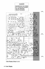
The circuit diagram in the SAMS Computerfacts document for the 5153 is an alternate information source, and that to me is easier to read. In that I see the 'dark yellow to brown' adjustment circuitry, and have placed that at [here].

In the IBM 5154, the 'dark yellow to brown' adjustment is done within the 5154's ROM.
 
Are you able to attach here a snip from the document?

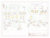
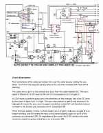
According to this site, the schematic here is the board that produces the dual color fix: https://www.aceinnova.com/en/electro...color-display/

It makes sense to me, because Hugo Holden put together a brown color fix board that uses only one of the same 74S05 chips. The board above uses two, which I'm assuming takes care of both the dark-yellow-to-brown, and the Color 9 black-to-dark-grey.
 
Last edited:
In the technical manual for the 5153, there's a correction board that gives you brown and dark grey colors.
I need someone to look for component P202 on any of your internal boards, ...
modem7 said:
I have looked at IBM's technical document for the IBM 5153, and in its circuit diagram, I cannot see what you are referring to. Are you able to attach here a snip from the document?
According to this site, the schematic here is the board that produces the dual color fix: https://www.aceinnova.com/en/electro...color-display/
I have just opened up my IBM 5153. There is no dedicated colour adjustment/correction board. As I expected, I can see the IBM 5153's 'dark yellow to brown' circuitry (Q201, Q206, etc.) on the main board, in amongst most of the other circuitry.
 
According to this site, the schematic here is the board that produces the dual color fix: https://www.aceinnova.com/en/electro...color-display/

It makes sense to me, because Hugo Holden put together a brown color fix board that uses only one of the same 74S05 chips. The board above uses two, which I'm assuming takes care of both the dark-yellow-to-brown, and the Color 9 black-to-dark-grey.


The table there on the aceinnova.com URL is a simplification of what actually happens in the IBM-5153's VDU color process circuitry.This is due to the circuitry design and mixing system. A while back when I was working with the 5153, I took the time to make measurements on the color process circuitry and document what was happening there.

Check on pages 22 & 23 of this document there is a different table constructed from measurements of the actual circuit:

http://www.worldphaco.com/uploads/FI...N_IBM_5155.pdf

From this article:

"When more than one color gets intensified, take Cyan for example (color 11), the value of intensification increases from 12% to about 24% for each active color when two colors are simultaneously intensified. This occurs because of the color channel interactions and the level at point Q on the circuit diagram shown above being affected by the amount of signal on each channel. Therefore, in this case, the output becomes equivalent to a white signal of 0.4 with an overlaid Cyan (equal blue & green) of about 1.24 – 0.4 = 0.84, (vs say the 0.72 for intensified red alone). So intensified Cyan for example has a brighter look than intensified red for two reasons, firstly it is brighter by approximately a factor 0.84/0.72 and secondly two CRT phosphors the green and the blue are simultaneously excited on the crt face. The situation is the same for any combination of two colors, for example Magenta or Yellow, as well as Cyan, and the level for each active color is 24% higher than in normal color mode".

With regard to the resistor in the Brown sub-circuit, my IBM-5153's both have the 560R. As Modem7 noted, there is no sub board, the circuit is part of the main board.

The sub-board I put into my scan rate converted 5153, was so it could display color 6 correctly when fed with an EGA signal, pages 15-17:

http://www.worldphaco.com/uploads/IN...OR_TO_AUTO.pdf

"The EGA 6 bit signal for the color Brown (color 6) the lines are logic level 010,100. This is a mix of R MSB and the g LSB. However, in the I,RGB system of the 5153 color monitor, Brown is 0,110 where the I signal is low, R & G are both logic high (giving low intensity yellow) and the 5153 monitor detects this state and lowers the green level in the gun amplifier system to display “Brown” instead of yellow. The above means that a Brown signal (color 6 in of an EGA color system) is displayed as intensified Red by a CGA “I,RGB” style color processing system. While all the other colors of the 0 to 15 set will display correctly using just the four I,R,G,B lines".

So that home grown sub-board is not to do with getting the CGA brown correct, it is about detecting EGA's brown, and making it display correctly on a scan rate modified 5153 VDU.
 
Last edited:
All I know is that my monitor is not displaying CGA/EGA brown, nor dark gray correctly: https://www.vcfed.org/forum/forum/ge...24#post1209524

In fact, all of the colors are out-of-standard. It looks like it has brown, but that's just a trick of the monitor, and the rest of the colors may look distinct, but for that they are much less distinct in-person.
I've tried Gauntlet and Space Quest I. There's blue armor in the Gauntlet title screen that is barely separate between dark and light. In Space Quest, it's the same thing, except the distinction is much worse. (Representative example below) I should be able to see a clear separation between light and dark, but it doesn't seem to be there.

In the image in the link, there should be a dark gray column of text in the center, but due to the color circuitry, it does not show up. (As I said in the link, as well, the "invisible" text only showed up when I had adjusted the color drives and balances beyond their normal settings.)
 

Attachments

  • colorexample1.png
    colorexample1.png
    76 KB · Views: 2
It must not be forgotten that this machine was barely "PC compatible" in the first place, it would not be at all surprising if Sanyo paid very little attention to making the monitor match a 5153. (Their previous even-less-compatible MBC-550 line of machines used simple 8-color RGB planar graphics with no intensity signal.)

I'm a little confused by this thread. Did you ever find schematics for this machine, or, at least, do you have the schematics for the monitor section and/or have you fully reverse-engineered how the monitor works as is? If the monitor has an "intensity" input and it actually digital then there's no way for you to tack a board in front of it that's going to "fix" brown for you. R is R, B is B, G is G, they're on or off. "I" is also on and off and it does a fixed thing to *all* of the others depending on whether it's set or not. If the monitor isn't producing sufficient contrast differences between "I" being set on or off (or you want a special case for the "brown fix") then you're going to have to figure our *specifically* what's going on in the monitor and adjust the circuitry that's already there. Maybe that's what this is about, but, it's not completely clear.

If you have a problem with both the intensity thing *and* you want the brown fix it might follow that the best approach would be to *first* figure out how to improve the intensity levels and *then* figure out how to get brown out of it, because the latter follows out of the former. (IE, you need to figure out how the monitor "adds" to the level intensities generally before you try to fix it for the special case.)
 
Yes, the motherboard(s) do(es) have an intensity signal.
(There are two boards: one controls video, drives, and ISA bus; the other one is the processor, timer, peripherals, and memory, mounted at a right angle with a pin header, similar to a normal ISA peripheral card.)

I didn't find any schematics for this particular system, but as I've said many times before, looking through the boards with my multimeter and looking at chips on the boards reveals that this system is extremely close in design to the 5150/60, not 1:1 in chip placement and components, but in gates and logic. It has the same timers, chips (8255, 8259, etc.), peripheral controllers, and basic circuits.

I also measured, and indeed there are voltages coming from all of the relevant pins (RGBIHV) on the built-in video connector. I also do get an intensity from either the built-in CGA board, or the EGA card I wired its feature connector up from. (Which is how I was able to get games like Space Quest to work.) It's slight on the screen, but the difference is there. (plus there IS a clear distinction between dark and light yellow, that I will say is certain.)

I did have an accident a few months ago, though, where I plugged in some of the power and signal cables into the wrong board headers, but I don't know if that would affect anything with color values...

In this I was also accidentally prepared with a LOT of components. I had planned to re-make the CRT board, because the one in the second computer in this lot I bought a while back was fractured, and wouldn't stand up to use. (I have copper-clad, and ferric chloride) I wanted to do this as a gesture of goodwill for Trixter, since he wanted one of these computers. Took me a while to find the blown components: A high-voltage protection resistor, which brought back the picture, and after a lot of searching, a transistor that was controlled by the brightness slider. I also did this for futureproofing.

Anyways, no, I do understand perfectly how these color signals work:

[MONITOR & CIRCUITRY]-------------[CABLE]-------------[VIDEO MOTHERBOARD/CARD]

I know I can't place a circuit anywhere in-between the video cable joins up with, either

MONITOR+CIRC---MOD BOARD---CABLE---VIDEO MOTHERBOARD/CARD
or
MONITOR+CIRC---CABLE---MOD BOARD---VIDEO MOTHERBOARD/CARD

Anything there will render the point moot, as we're still manipulating TTL bit switches to turn colors on and off for mixing on-screen, and not changing analogue color levels. (which are basically "hard-coded" according to the components on the board.)

I'll take a much closer look at the CRT board later, and see if there's any substantial similarity between it and the 5153. Although, I did find a similar IC in the monitor circuitry that seems to be integral in controlling the color logic, a 74S05, which is also present, twice, on the schematic I posted.
 
Last edited:
Anything there will render the point moot, as we're still manipulating TTL bit switches to turn colors on and off for mixing on-screen, and not changing analogue color levels. (which are basically "hard-coded" according to the components on the board.)

I'll take a much closer look at the CRT board later, and see if there's any substantial similarity between it and the 5153. Although, I did find a similar IC in the monitor circuitry that seems to be integral in controlling the color logic, a 74S05, which is also present, twice, on the schematic I posted.

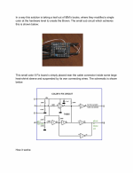
Maybe this is where the confusion is, see attached image from one of he articles I linked. The 5153 is unique in the way it processes color signals, it is not all digital. Due to the mixing of the color and intensity signals at the open collector gate outputs, with resistors, and the way the channels interact, the output levels take on intermediate values, not just the equivalent of 0 and 1 and are effectively Analog or at least pseudo-analog to drive the CRT's guns. This is what gives the unique color intensity rendition on the 5153.

So if you wan't to make any other color VDU act like a 5153 for color & intensity rendition, you would have to modify the circuitry to conform to this basic design. As noted, if one, two or three of the colors are intensified, the alters the intensity increase of all the colors due to the interaction at point Q in the circuit.
 

Attachments

  • 5153.jpg
    5153.jpg
    195.8 KB · Views: 2
With regard to the resistor in the Brown sub-circuit, my IBM-5153's both have the 560R.
I revisited the SAMS document, and in the schematic notes is, "Value in () used in some versions."
I modified the R252 note in my diagram [here] accordingly.

I took a look in my 5153. R252 in that appears to be 620 ohms, a third possible value. See [here].
 
I revisited the SAMS document, and in the schematic notes is, "Value in () used in some versions."
I modified the R252 note in my diagram [here] accordingly.

I took a look in my 5153. R252 in that appears to be 620 ohms, a third possible value. See [here].

All of those values are close enough to give a similar result in practice, operating in the 5153's circuit.
 
All right, it took a while, but I mixed your detector board with what I think is the color corrector board in the 5153 (which apparently corrects TWO colors: Dark Gray and Brown), Hugo. I need some checking, though, because I don't have the patience to follow the pathways and figure out the logic. I may have made some errors, but some of the color bit connections to the CRT Driver (Main) PCB were made by guessing based on other connections that were present in the 5153's schematics.

MY SCHEMATIC:

Click image for larger version  Name:	Color Fix + 21.8KHz Detector PCB.png Views:	0 Size:	363.8 KB ID:	1228189
HUGO HOLDEN'S 21.8 KHz DETECTOR BOARD:
Click image for larger version  Name:	Detector Board (HH).png Views:	0 Size:	558.9 KB ID:	1228190
HUGO HOLDEN'S COLOR CORRECTION CIRCUIT:
Click image for larger version  Name:	Color Circuit (HH).png Views:	0 Size:	428.8 KB ID:	1228191
ORIGINAL IBM 5153 COLOR CORRECTION CIRCUIT:
Click image for larger version  Name:	5153 Color Display Correction Board.png Views:	0 Size:	405.7 KB ID:	1228192
 
The circuits you posted above from my articles and the one you have drawn including some of this really do not relate to the problem you appear to have. These circuits were designed to make a 5153 VDU detect EGA, go into a scan conversion mode and display colors correctly at least the 8 standard and 8 intensified ones, including color 6, on a reduced sized scanning raster.

The problem you have, I gather, but it is not 100% clear from the posts, is that you have another brand VDU, with RGB and I processing that does not give the same color rendition as a genuine 5153 monitor , is this correct, is this your problem ? Or do you have a real 5153 that is not working properly ?

If that is the case, that you are wanting another brand of VDU to act like a 5153, the circuit functions that needs replicating or adding to your VDU is essentially the one I attached in post #9 from the 5153's schematic. It is this arrangement, and the signal it receives from the low intensity yellow detector transistor on the board, that gives the 5153 monitor its unique color rendition. (This is not related to the "Color six fix circuit" or the scan rate 21.8kHz detection circuits, these circuits relate to a different problem of scan converting a 5153 monitor so these circuits won't help you).

Also to get the same result as a 5153 VDU, with another VDU, the intensity signal must also dynamically deactivate the contrast control to full contrast, which was another unique feature of the 5153, if you try a 5153, you will find that the contrast control has no effect on intensified colors, very interesting. It means that the level difference between intensified an un-intensified colors can be increased if the contrast of the un-intensified colors are reduced by the contrast control being at a lower setting. I have never seen any other color VDU that does this.
 
Last edited:
The problem you have, I gather, but it is not 100% clear from the posts, is that you have another brand VDU, with RGB and I processing that does not give the same color rendition as a genuine 5153 monitor , is this correct, is this your problem?

Yes, this is my problem. My computer's monitor is internal (It is a Sanyo MBC-775 computer), and the CRT controller board does not allow two colors to show through properly. Color 6 seems to show as dark yellow, not brown. Color 8, Dark Gray, seems to not show up at all, and in-fact, where it should appear shows up only if the color drive pots on the electron gun socket PCB are adjusted.

Furthermore, to my eyes, I do not have good contrast between the two levels of colors.

Although the two levels of colors look different here, they look much closer in tone IRL than in a photo:
https://www.vcfed.org/forum/forum/g...bc-775-internal-monitor?p=1209524#post1209524

This is more like how they tend to look:
https://www.vcfed.org/forum/forum/t...-a-particular-component?p=1211364#post1211364
 
It could be difficult to work out what is happening. I think it would require firstly that your VDU was set back to normal color balance, then to display a test pattern of colors, and photograph it, like the photo on page 13 of this article, this can easily be done plotting boxes in BASIC:

https://www.worldphaco.com/uploads/F...N_IBM_5155.pdf,

Then feed the same signals from your computer into a real IBM5153, and then photograph that result, then compare the two side by side to see what the actual difference is. But likely it will largely relate to the way the 5153's circuit deals with low intensity yellow and the way it pushes the contrast to max when the intensity signal is high.

(or if it is an EGA mode you would need to do the comparison with a 5154 monitor)
 
Last edited:
Then feed the same signals from your computer into a real IBM5153, and then photograph that result, then compare the two side by side to see what the actual difference is. But likely it will largely relate to the way the 5153's circuit deals with low intensity yellow and the way it pushes the contrast to max when the intensity signal is high.

Oh, you mean only the Color 6-fix circuit you created would probably fix my problem? The way I interpret that bolded part is that with the color-fix circuit, the brightness difference between colors with intensity-off and intensity-on would be much higher, and thus would also fix their saturation, and be more in-line with later video card BIOSes?


There is already an LS05 on the CRT board, so maybe just one extra is what it needs. (I've seen people call the non-compatible CGA standard "naive")

Well you see the color six fix circuit was designed to correct the EGA signal for the yellow vs brown, not a CGA signal, from the article:

This color 6 anomaly can be corrected by using the r LSB signal (which is available at the cable inside the 5153) along with the g LSB signal to deactivate the intensification “I” and add Green. This ensures the 5153 monitor “sees” low intensity Yellow” or 0,110 and displays Brown correctly when presented with an EGA 010,100 Brown signal.

So whether this circuit could help you at all would depend on whether the source signal you are referring to is EGA or CGA, which I have not been clear on from your previous posts.

As noted before, if you have a CGA signal from your video card, driving some VDU, and it is not displaying it as an 5153 monitor would display it (because the VDU does not have the low intensity yellow detector or the contrast control deactivator) then the only way to fix that would be to re-create these circuit features of the 5153 monitor in the VDU. Which means you would need to detect low intensity yellow and use it to lower the green level, in a similar mixer to the 5153 (as shown on post #9), and use the intensity signal to push the contrast to full for all colors. It is easy to see how they did this in the 5153's circuitry.
 
Well you see the color six fix circuit was designed to correct the EGA signal for the yellow vs brown, not a CGA signal, from the article:...

I would say that I have both. I was able to use the feature connector on an EGA card to pipe the digital signals into the internal monitor's normal connector. (It's basically a CGA/EGA port without the DE-9 connector, and the card has a CGA compatibility mode.)

I'll see what I can do as far as the main VDU/CRT board is concerned, though, to see if it copies the schematic.
 
Ok, I finally got a program capable of showing all 16 CGA/EGA colors, and it seems I was right the first time. I have the naive version of the CGA circuitry, and the dark grey does exist. It's just very dark. Is there a way to readjust the colors so there's more of a contrast between the two intensities? (Maybe changing resistors?)
 
Last edited:
Back
Top