• Please review our updated Terms and Rules here

AIM-65 Video Output Success.

Hugo Holden

Veteran Member
Joined
Dec 23, 2015
Messages
4,749
Location
Australia
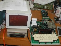
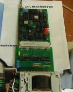
I have successfully made a working replica of the Rockwell RM-65 CRTC video card and the Adapter card to make it work with the AIM-65.

I had no idea how good this CRTC card was, until I read the user manual, all sorts of options for video formats, but even better, a large section of the firmware, on the on-board ROM, is dedicated to supporting its function with the AIM-65 computer. So it doesn't use any of the AIM-65's processor time, required by other video cards requiring a software protocol to run.

Out of all of the vintage computer replica cards I have made so far, this one was by far and away the most challenging, because it is a 4 layer board. I had to create the invisible 2 layers and in one of those layers is an 8 bit data bus. It stretched me and my pcb maker to the limit and took some months to finish. It would not have been possible without help from member dfnr2 who provided photos & X-rays of the original board, and importantly, the ROM dumps. Thank you.

Now it is working, it was all worth it.

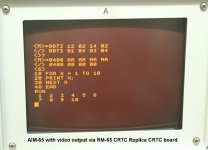
I have attached some images, using it with BASIC on the AIM-65. Interestingly, much like the dilemma with BASIC pointers that was recently solved to allow BASIC on the AIM 65 to run a Commodore 1541 disk drive, with the AH5050 system (INIBAS PROGRAM), to operate this card with BASIC running in the AIM-65, some pointers in memory need changing. But in this case, it was no mystery, because Rockwell explained how to do it in the CRTC user manual, otherwise it would have been awkward for me because my strengths are only on the hardware side of the technical challenge and I struggle with the software.

I am doing up a very detailed article on it, I will add the link to this thread when it is ready.

CRTC1r.jpg CRTC2r.jpg CRTC3r.jpg
 
Nice job Hugo (again)!

You should also be able to adjust the WIDTH so it aligns with the width of the screen offered by the RM-65.

You can do this when BASIC starts (question: WIDTH?) or via a memory POKE.

I have seen your orange monitor construction on your website - it is even better in the flesh (so to speak)...

Dave
 
@Hugo: This is truly an impressive piece of work. I am still amazed by how quickly you were able to reverse this complex board. And it seems like it pretty much worked the first time, so that you were deprived of the joy of debugging the board. Looks like you'll need to find a more complex project now :)
 
Hugo sent me an adapter board for my RM65, so that I might have a working board as a comparison for his replicas as he debugged them. Ironically, he got the replica up and running before I even had a chance to try the adapter board.

Of course, the board worked, and I was able to boot into BASIC last evening. The manual outlines the firmware initiazlization required to produce video output. Once the routine (in ROM) is executed--just a few steps in the monitor--then everything displays seamlessly on the screen. The manual has a procedure for starting BASIC: first start BASIC, then exit, initialize the CRTC, then warm start BASIC. So the integration is not exactly seamless, but not too bad. The manual warns that cold starting BASIC with the CRTC in operation may interfere with the CRTC settings/operation, but I tried it and it seemed to work. However, I bypassed the memory test, which I suspect would be the issue with cold-start.

This replica is really an incredible addition to the AIM 65. With the Commodore disk drive and the RM-65, it's possible to put together a really nifty system.


in_operation.jpg - Running BASIC
 
If one of you could post the start-up code required - that could be added to something like an INIRM65 file on the disk so that you run it and it initialises both the RM65 and BASIC in one go - setting the WIDTH etc. accordingly.

Dave
 
Great stuff Hugo. You wouldn't want to part with an extra PCB for the video card. I'd not be using it with my AIM though, so wouldn't need the adapter. I'd use it with my back plane.
Dwight
 
If one of you could post the start-up code required - that could be added to something like an INIRM65 file on the disk so that you run it and it initialises both the RM65 and BASIC in one go - setting the WIDTH etc. accordingly.

Dave

All the initialization code is in the ROM, at $9900.

The startup process is:

- set screen geometry
- set the terminal mode
- Jump to $9900 to initialize the CRTC

The screen geometry is determined by the value at $035A. From the manual:
ValueRows/ColsScreen LinesJumper E2
025 x 80625B
122 x 72525B
225 x 40625A
316 x 40525A
4User defined525 / 625A / B
>422 x 72525B

What I'm calling the terminal mode, the manual calls the "AIM65"
variable. This value tells the CRTC terminal emulation software whether to send
code to the AIM-65 input processing routines, such as the line parsers for
BASIC, the monitor, PL/65, etc. The values are:

0) Skip the AIM-65 input processing code


1) Call the AIM-65 input processing code, sending the CR ($0d) but ignore LFs
($0a). Apparently this avoids a double CR/LF with programs that write out a
CR/LF on receiving CR.

>1: Call the AIM-65 input processing code, sending both CR and LF. This seems to
be the correct choice for the monitor, Assembler, Editor, BASIC, and FORTH


So the sequence suggested in the manual is

In the monitor:
- store $05 in $035A
- store $02 in $0357
- jump to $9900
 
To clarify, the firmware contains line editing software that permits movement within lines, and around the screen, and allows editing of lines on the screen, sending lines to the AIM-65 input processing code when CR is hit (or LF, depending on the configuration).
 
Thanks for all the kind words.

The display geometry I selected for the photo I posted was the 16 x 40, 525 line & jumper A by putting 03 at $035A.

I'm writing up the article in enough detail that anyone else should be able to fairly easily replicate it second time around. My pcb maker can supply the boards to anyone on mail order, he is doing this now with previous pcb's I have designed, for example the PONG pcb.

It does take a while to collect up all the different IC's from ebay, some are less common like the 74S113 and not in the average junk box. The original Xtal and other small capacitors are readily available, and the Euro connector is still available. Though the right angle connector on the adapter board that attaches to the AIM is hard to get, but I solved this by using the type intended for wire wrap and making a small tool to bend the pins neatly at a right angle.

The details should be available within 1 week.
 
So the sequence suggested in the manual is

In the monitor:
- store $05 in $035A
- store $02 in $0357
- jump to $9900

Actually there's a bit more to the initialization than I originally posted.

BASIC (and other languages) store some variables in page 2, below the program storage area. To avoid conflicts, the CRTC firmware stores its variables in page 3, so the storage area needs to be set above this, to avoid, for example, a BASIC program of more than a few lines overwriting the CRTC variables. I think that cold-starting BASIC resets the start of program space to $0211, which is why the manual warns against cold starting BASIC after configuring the CRTC.

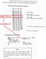
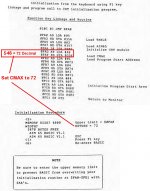
So the full setup, per the manual, is:
  • Cold start BASIC, then exit. Set the line width as desired (default 72)
  • Exit back to the monitor
  • Store $05 (or other appropriate display geometry setting) in $035A
  • Store $02 in $0357 (to send the typed line to BASIC)
  • Store the desired line length in $035E to match the BASIC line length ($48 = 72)
  • Store the new base of program space ($0400) at $73
  • Store the new base of variable storage ($0402) at $75
  • Warm start BASIC
The manual contains a recipe for doing these steps manually, as well as a short code snippet that can be bound to F1 to accomplish this programmatically.
 
Most of this ‘malarky’ is what we have already gone through with the AH5050 disk interface.

I just need to checkout that the RM-65 VDU and the AH5050 disk interface can coexist together. They both have their individual page 0 and ‘other’ variable storage requirements.

Thanks for the ‘heads up’ though. One foreseeable problem (to auto-starting that is) is the RM65 ROM initialisation entry point returning to COMIN at the conclusion. There is mention of a programatic version that performs a RTS, so this may be an alternative. I will download your manual scan and have a read when I get a bit of free time.

Dave
 
Last edited:
Most of this ‘malarky’ is what we have already gone through with the AH5050 disk interface.

I just need to checkout that the RM-65 VDU and the AH5050 disk interface can coexist together. They both have their individual page 0 and ‘other’ variable storage requirements.

Thanks for the ‘heads up’ though. One foreseeable problem (to auto-starting that is) is the RM65 ROM initialisation entry point returning to COMIN at the conclusion. There is mention of a programatic version that performs a RTS, so this may be an alternative. I will download your manual scan and have a read when I get a bit of free time.

Dave

Apart from the BASIC page storage, vs the RM65, one of the functions of the CRTC's ROM firmware is that is has an "AIM-65 Assembler reformatter" that outputs an AIM assembly listing as a 60 column format with the addresses on each line.

Of course using the AH5050/1541 drive, the AH5050 ROM takes the place of the Assembler ROM on the AIM-65 motherboard. So those two systems at least as it stands would not work together.
 
Good point.

Unless you can find a copy of the relocated AIM-65 assembler ROM for use with the AH5050?

Put that on your Santa list for Christmas...

Dave
 
Good point.

Unless you can find a copy of the relocated AIM-65 assembler ROM for use with the AH5050?

Put that on your Santa list for Christmas...

Dave

I would "guess" this would require the full disassembly of the AH5050 ROM, then, fixing up all the address jumps and reassembling it at the new address and cutting a new ROM?

A while back I was sort of confronted with this issue. I wanted to run BASIC at a higher address in my SOL-20 because I had it in ROM in a Bytesaver board . For that problem I kept the original BASIC program and used a block move problem I put into spare ROM space to down shift it to its original address.

That sort of thing would not help with this problem, but the issue made me realize how tricky it is to reconfigure an entire program to run from a new starting address (at least for me to do it anyway). Though its easier if the program is available with relative addresses, to reassemble it at some new address. I managed to do this with some simple 8080 programs like TRAIN and put them at higher address in ROM in my SOL-20.

On another topic with this RM65 CRTC card: I noticed that one of the features of the card is to provide reversed video (white background with black letters). The usual way to provide a logic control of this function is to pass the video signal (not the syncs) via an XOR gate. This way if you manipulate the logic level of the other XOR gate input, it converts the XOR into an inverter or a non inverter gate. Looking at the RM65 schematic, they have this XOR in the circuit to enable this option. Though I have never much liked the illuminated background black character option on a CRT, but I guess some might like it. I think, from memory, the Sinclair ZX-81 was like this.
 
Last edited:
The work has already been done. The trick is to find one of the little blighters...

If you look at page 2 of http://cini.classiccmp.org/pdf/Rockw...20AH5050-2.pdf you will see a part number of AH5050-A (which is the assembler ROM relocated to run starting at a base address of $B000).

Early microprocessors didn't really support Position Independent Code very well at all. Interestingly, with the introduction of the NAS-SYS monitor for the NASCOM computer (a very good British Z80 machine - but (of course) I am biased :)) this added a relative subroutine call etc. using the 8080/Z80 restart instructions. This didn't solve all of the problems in one go, but it did help...

Yes, the video invert was always strange. As you stated, the general way was to invert the video output signal. But, when I saw a different way, that did cause a bit of head scratching to start with!

Dave

Yes, the AH5050A would be a very rare animal, considering how rare the standard one was.

One thing that really surprised me was that one of the World's first s-100 graphics cards, the Matrox ALT 256, did not have reverse video. The only way I could get it was to re-format the entire image file, have a look at the DeLorean sketch on pages 8 & 9 of this article:

https://www.worldphaco.com/uploads/MATROX_ALT256.pdf

It would have been so much easier with the XOR gate in the video. Though it would be dead easy to add the XOR to the Matrox card but that would make it non-original , so I probably wouldn't do that.
 
Last edited:
Here is the program from the manual that suggests how to use the AIM-65's F1 key to execute the CRTC's setup procedure, but first enter BASIC with <5> ultimately run the program with F1 key, and then warm start BASIC with <6> RM65x.jpg RM65x.jpg
 
That looks really cool, Hugo. I look forward to reading your article!

Thanks,

I'm writing it up now, the most difficult part for me is explaining how they did the software side of it, to integrate it so well into the AIM-65 hardware, the Assembler & BASIC.

Rockwell obviously put a lot of thought into the problem of a video display, both into the elaborate hardware (with the 4 layer pcb) and a large number of IC's and their firmware. And they also made it multi-video standard, 525 and 625 line systems so it could work in the USA or Europe.

To me, this RM-65 CRTC card is very impressive. On the software side, Rockwell also allowed for entry procedures into FORTH & PASCAL, which I could say would be out of the scope of my article.

If it is just circuit tracks & logic gates, I have a lot less difficulty with it.
 
Back
Top