Hello!
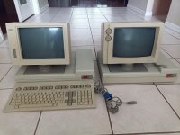
I recently acquired two Wang Pm-004 displays, each with a Wang 4220 bases (I assume for controlling and rendering terminal connections?) .
Here's a picture of each.

I want to get them working, but I am missing 2/3 of the required display cables and I'm curious if anyone knows anything about these to help me find/create replacements.
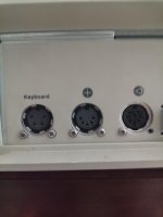
The bases are identical, with these 5 and 8 pin DIN connectors shown below with these symbols (I'm guessing the '+' is beam control and the '<)' is the scanning signals). The Monitor with the knobs has the same connectors on the bottom of this, and I have the 5 pin + connector, but not the other one. I don't have a multimeter available to me for a few days to check if the given cable is a straight through or cross over cable, because I want to guess that the same engineers would use the same type for the other one. I'm hoping to be able to buy something like this [https://www.amazon.com/Ancable-Male...ywords=8-pin+din+cable&qid=1624050569&sr=8-3] to replace it.

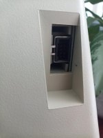
The monitor with no knobs has a connector with 10 pins I've never seen before, here is a picture of that:

So here are my questions:
1. Does anyone have documentation about these things, as most internet searches barely return anything besides old ebay listings.
2. Would that simple 8 pin DIN cable work for that monitor, and if it might not, should I worry about that damaging the monitor if I tried.
3. What is that weird 10 pin connector called and/or what is the pinout relative to the DIN cables?
4. There are 2 sets of 10 dip switches on the back of the 4220 base, how do I figure out what those do?
Probably all of these would be answered with the docs from question 1, or some deconstruction and reverse engineering, but I welcome any advice you may have.
Thank you
I recently acquired two Wang Pm-004 displays, each with a Wang 4220 bases (I assume for controlling and rendering terminal connections?) .
Here's a picture of each.

I want to get them working, but I am missing 2/3 of the required display cables and I'm curious if anyone knows anything about these to help me find/create replacements.
The bases are identical, with these 5 and 8 pin DIN connectors shown below with these symbols (I'm guessing the '+' is beam control and the '<)' is the scanning signals). The Monitor with the knobs has the same connectors on the bottom of this, and I have the 5 pin + connector, but not the other one. I don't have a multimeter available to me for a few days to check if the given cable is a straight through or cross over cable, because I want to guess that the same engineers would use the same type for the other one. I'm hoping to be able to buy something like this [https://www.amazon.com/Ancable-Male...ywords=8-pin+din+cable&qid=1624050569&sr=8-3] to replace it.

The monitor with no knobs has a connector with 10 pins I've never seen before, here is a picture of that:

So here are my questions:
1. Does anyone have documentation about these things, as most internet searches barely return anything besides old ebay listings.
2. Would that simple 8 pin DIN cable work for that monitor, and if it might not, should I worry about that damaging the monitor if I tried.
3. What is that weird 10 pin connector called and/or what is the pinout relative to the DIN cables?
4. There are 2 sets of 10 dip switches on the back of the 4220 base, how do I figure out what those do?
Probably all of these would be answered with the docs from question 1, or some deconstruction and reverse engineering, but I welcome any advice you may have.
Thank you


