• Please review our updated Terms and Rules here

4 floppies with DPDT switches on power cable?

Phase

Member
Joined
Sep 1, 2021
Messages
19
Hi everyone,

Pardon the silly question...

If I managed to put together a cable that allowed me to connect 2 drive "A:", then the cable twist, and then two drive "B:" (4 physical drives), would we be able to select which pair of 2 drives we want, prior to boot, by using a couple of DPDT switches on the power cables going to the 4 drives (on the +5V and +12V leads)? Or do we have to worry about enabling/disabling additional wires in the floppy cable itself?

Thanks!!
 
Depends how intelligent the BIOS is. Some get upset if you specify a drive as 1.44mb 3.5" but it's a 360k 5.25". The solution there is just make sure your drive switches are set to drives matching your CMOS config when you power up and then you can toggle between the drives all you want afterwards as long as you use drive type/capacity flags in whatever program you are using to force it to use a mode. Since I'm assuming you only tapped into the basic select lines there shouldn't be any problem with four drives sharing the same ribbon cable as the other drives won't react to commands unless their specific Drive/motor select lines are polled.
 
No, see my earlier post for a bracket to switch a single floppy to an alternate drive: here. There's no reason that it couldn't be for more than one floppy. Floppy outputs are all open-collector and conditioned on drive-select, other than motor-on. The only real thing you have to be careful of is termination--there has to be a pullup somewhere in the floppy chain.

Using an n-way DP switch (e.g. a 2 pole rotary switch), you could select among n floppies (up to the loading limit of the floppy bus).
 
After installing Sergey's XI-8088 into a case I ran into the problem that the 1.44 MB drive had problems with reading and writing 720 KB floppies. So I installed a 720 KB drive parallel to the 1.44 MB one using a DPDT switch that switched the motor and select lines. And that worked like a charm. OK, like NeXT mentioned, I have to run the set-up for the CMOS after every change.

But I must admit that I like Phase's idea, just switching the power lines. But what about the non-powered drives, can they influence the bus in a negative way?
 
You're much more secure switching the DSx and MOTOR lines with the same DPDT switch. At least you don't have to worry about how unpowered signal lines will interfere. And my method works,.

This reminds me of the "external drive" cards used on some of the lower PS/2 systems. The DOR on the PC controller is a write-only register. A card acting as a pass-through for all signals except the drive select and motor lines had its own fully-decoded DOR supplied the extra drive signals. Since it's a write-only register, it didn't affect the operation of the motherboard controller.
 
Okay, so, if I got it right I could make a 34 pin cable with one female (F1) and two male connectors (M1, M2). Then have a DPDT switch (S1) that commuted the "Motor enable A" and "Motor enable B" signals so that only M1 or M2 gets those signals. Then hook up a regular floppy cable (CB1) to M1 and a second regular floppy cable (CB2) to M2. With S1 I would activate either the 2 floppies connected to CB1 or the 2 floppies connected to CB2. Caveat being I may need to run the bios setup when switching.

What is the best way to patch a cable in that way? The conductors are so tiny.
 
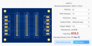
If the above works, we could use a standard floppy cable extender, to hook up to a PCB, that hooks up to the 2 standard floppy cables. I googled pcb manufacturing and it seems that we can get 10 of these done for under $100. Then we would just have to solder 6 leads to the DPDT switch... or maybe have them do that as well. Thoughts?

Screenshot 2021-09-02 152623.png
 
What is the best way to patch a cable in that way? The conductors are so tiny.

The best way is not to patch them at all. Just get a small prototype board and some male headers. Use an extra floppy cable to connect from the FDC to the board and then another (or two) to connect to your floppies.

I'm pretty surprised that no one commented on my original thread. It would seem that lots of folks would want to do this.
 
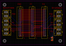
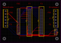
I ended up drawing the board. I need to check that I selected the correct components, make sure it will all fit, and that I can source them. I ended up building in the option to switch the drive select cables just in case since the cable twist twists those as well. If not I can just connect them with a couple of leads... or may be I'll add a couple of jumpers so that if it is not needed i can use the same board and not bother to weld the set of 3 extra connectors on the right.

Screenshot 2021-09-02 202331.png
 
I'm having trouble looking at your board layout. It should be pretty simple with a double-sided PCB. Do you have a netlist or schematic that we can check?
 
I'm not sure why the pictures are not current there... this is what it should look like

Screenshot 2021-09-02 210953.png

Screenshot 2021-09-02 210953.png
 
I'm a little puzzled about what will go into the Fx and Xx areas--if they're jumpers, I just take another 0.1" 2-row header (6 rows) and use regular 0.1 jumper blocks on those.

I also wouldn't leave the wiring to the autorouter. Leave one side for grounds and just run vertical long pads and tie all of the odd-numbered pins there. It looks like the autorouter wants to put grounds on both sides.
 
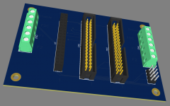
Cool. Thanks for the tip. This time I figured out how to find the right components. I manually routed the ground and had the autoroute do the rest. The screw terminals on the right would go to the DPDT switch. There is the option of using a 4PDT switch by also using the screw terminals on the right. Those would enable redirecting not only the motor enable, but also the drive select signals.

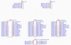
FDC goes to the board and it is supposed to be a floppy cable extender. F1 and F2 are regular floppy cables, each connecting to 2 drives. The DPDT (or 4PDT) switch enables either the cable plugged in on F1 or the cable plugged in on F2. If we do not care that the drive select signals go to both cables then we can plug all 4 jumpers on the lower right -- which is neater than jumping them on the screw terminals on the right.

Thoughts?

schematic.png

pcb.png

3d.png

parts.png
 
I'm pretty surprised that no one commented on my original thread. It would seem that lots of folks would want to do this.
Probably not. No offense meant but I think it is too much work. In my case it was easier to take an old P2 PC that runs XP and supports two drives. I removed the CD-ROM and installed a 1.2 MB drive instead. And now I use it mainly to to turn floppies into images or vica versa. The images can be distributed to my other PCs where they can be used on emulators.
 
... to hook up to a PCB, that hooks up ....
Why didn't I think of that? To the drawing board!

Background info: I want to create a PC with at least eight floppy drives: two of each of well known standard drives. Sergey's special FDC BIOS handles two FDC cards that support four drives but I only found one so far. AFAIK only XTs can handle four drives (coorect me if I'm wrong). But using PCBs I can use a more modern PC that is able to support at least two drives and capable of running XP at least (needed for network connectivity).

So thank you for the idea!
 
Last time I needed 4 floppys I simply installed an Adaptec AHA-1542CF SCSI controller and set its floppy port to act as a secondary one...
 
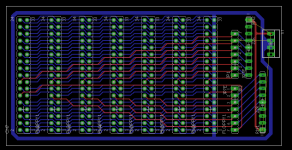
I did some drawing and came up with this:

t.png
A card that enables a user to select one drive out of six. The idea is that you connect a PCB to each of the connectors of the original floppy cable that you normally connect to a drive. That enables you to select two drives out of a total of up to twelve.
The original connector you must connect to CN1, the most right 34-pins connector. The other six must be connected to a drive. JP1 and JP2 lead to a 2 pole/6 positions rotary switch that enables you to select the switch. RN1 and RN2 can be used to pull up the unselected lines, X1 provides the needed +5V.

Why twelve drives? Background: the base idea I had was having a PC with eight drives, two of each of the well known ones. This enables me to make perfect disk copies by using a matched drive for both reading and writing a disk. Not only disk copies but also copying from one type to another one. The main idea was using two FDC cards that were able to handle four drives each. And then I obtained a Gotek....
But the main reason to chose for the number twelve is simple: I have these 2/6 rotary switches laying around, why not using their full capacity? And it solves my Gotek "problem" (and possible future ones).
 
Probably not. No offense meant but I think it is too much work. In my case it was easier to take an old P2 PC that runs XP and supports two drives. I removed the CD-ROM and installed a 1.2 MB drive instead. And now I use it mainly to to turn floppies into images or vica versa. The images can be distributed to my other PCs where they can be used on emulators.

I guess I'm a bit different. I have two shelves full of external drive boxes, from 8" units, to CF2 3", will 100 tpi, 96 tpi and 48 tpi drives in varying capacities. Last time I tried to fit an 8" floppy into a 5.25" drive, it just wouldn't fit, no matter how hard I crammed it in that little slot. ;)
 
Back
Top