• Please review our updated Terms and Rules here

Pertec 8840A 9-Track Tape Transport Repair Project

firebirdta84

Experienced Member
Joined
Jun 26, 2013
Messages
244
Location
Central Iowa
My friend Dominique in Belgium is repairing his Pertec 8840A 9-Track Tape Transport (Part of his Nixdorf 620 system). On a recent visit the week of Thanksgiving, the transport went from working flawlessly to quickly degrading. Symptoms were:

* Rewind not stopping, tape not loading properly
* Tape not stopping at the end, and pulling the tape right off the end of the source reel.

Essentially, it was obvious that the machine was not detecting the BOT Beginning of Tape (Or BOM, Beginning of Media, depending on your nomenclature), or the EOT/EOM.

And so began the long journey to diagnose and repair this wonderful beast.

Unfortunately, this transport breakdown happened just on the eve of my departure, so I wasn't able to lend much in-person assistance to get it working again....

We don't have an actual service or technical manual for this model, so we are using the closest equivalent that we can find on bitsavers.org (thank you Al & Team!!!)

http://www.bitsavers.org/pdf/pertec/...x60A_Aug82.pdf

And here are overall pictures of this transport, for reference:
https://drive.google.com/drive/folde...bmo5Pzr9xFYeSm

So, to help, I wanted to take our notes of the diagnostics and repairs so far, and share them here, so that the "Masters of the Tape Transport Systems" could weigh in their thoughts and expertise.

The following post will be a recap from Dominique's diagnostic and repairs so far...
 
Last edited:
Here is the next episode of my troubleshooting adventure

1. Fuse blown and discovery of dead Q48 (2N6051 PNP)

2. Q48 replaced by an equivalent (BDX66C)

3. The Load process starts normally (extension of the tension arms) but the Supply Reel only turns forward, tension arm inoperative, no polarity inversion of the Supply Reel, the tape drive of course does not manage to put the magnetic tape in tension.

4. The Take up reel turns in the good direction (clockwise), tension arm operating correctly, depending on its position, the motor speed changes until the motor polarity is reversed.

5. Discovery of a dead light bulb in the optical sensor of the tension arm of the Supply reel (Yes ! That's it!)

6. Replacement by a led, same result (maybe my led does not give off enough light?)

7. Tests of the sensor with the led on the Take Up reel, my sensor is working (so this was not the reason for the failure)

8. I decide to interchange Q43 and Q49 (2N6058 NPN) so as to make operational the supply reel instead of the take up reel and thus have the confirmation that the problem is at the level of Q49 (Q48 & Q49 are matched pair of PNP NPN transistor supplying the reverse polarity for the supply reel motor).

9. The fuse blown again! I do not understand why !

10. I decide to note the color of the wires on my HEATSINK ASSEMBLY picture and unsolder all the transistors.
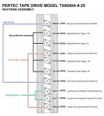

Pertec-TX8840A-9-25-Heatsink-Assembly-V2.jpg - Click image for larger version  Name:	Pertec-TX8840A-9-25-Heatsink-Assembly-V2.jpg Views:	0 Size:	158.9 KB ID:	1235495


11. I discovered that my new Q48 (BDX66C) was killed by this interchange of 2N6058 (therefore between Q43 and Q49).

12. With the multi-meter I measure that all the other transistors are good (but finally a multi-meter is it enough to test the good health of the power transistors?

13. I resolder everything with a new Q48 (a BDX66C as equivalent for the 2N6051), As these 2N6051 seem fragile, I also replace Q42 with a BDX66C I put new insulators on some transistors because their mikas seem a little crackled (can be the cause of a short circuit).

14. I replace the fuse.
15. During the test the Load procedure also starts, this time it is the Supply reel which functions normally but the Take up reel which unwinds the tape (clockwise) instead of winding it (counter clockwise) and it is also this times the tension arm on the side of the Take up reel which no longer responds. In fact it's the exact opposite situation of point 3. and 4. described above.

16. By testing the motor polarity reversal by manually retracting the tension arm of the Supply reel, it suddenly stops functioning, the motor continues to vary speed but does not go in the other sens of rotation.

17. I order two BDX67C equivalents to replace the two 2N6058 in Q43 and Q49 and in the process, I order two more new BDX66Cs (I am starting to doubt my ability to know when they are functional or not. I have high hopes, BDX66C and BDX67C are "matched pairs".

18. I resolder the 4 new components, I test with a piece of magnetic tape in front of the optical detector to start the LOAD sequence, the tension arms are deployed, and by pressing the LOAD button, the two motors start to run, I 'manually actuate the tension arm, reversing the motors polarity, YES ! it works !!
19. Full of hope, I tested with a magtape this time: He almost succeeded in putting it under tension, but the arm tension touched the limit switch, I said to myself: "no big deal, the positioning values ​​of the arms must be readjusted ", before that I still try to tension the tape, but oddly enough, instead of having the same result, it works less and less well.

20. Even before having been able to check the adjustments of the tension arms, it stop working at all, the reels turn only in one direction:

- The Supply reel clockwise
- The Take up weel counter clockwise
If I activate the tension arm, I can vary the speed and even stop the motors, but neither start in the other sens of rotation.

At this stage I am wondering if I have not again gunned my new BDX66C or BDX67C equivalents because since the replacement I have these motor movements described above which works perfectly now, with the speed gradation, I just lost the opposite movement on these two motors, I wonder if these BDX66C & BDX67C are beefy enough. With what type of more powerful transistors could I replace these fragile BDX66C and BDX67C?

I also wonder if the cause of this failure would not be elsewhere now, by dying, the first Q48 impacted the transistors of the board tape control? For example the transistors that we can observe as being close in the circuit below, I am thinking of Q39 (2N3053) - Q43 (2N5323) for the Take Up reel circuit or even of Q45 (2N3053) - Q46 (2N5323) for the Supply Reel circuit:
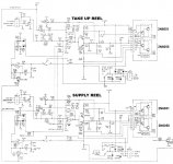
Pertec-TX8840A-9-25-Reel-Supply-Schematics.jpg - Click image for larger version  Name:	Pertec-TX8840A-9-25-Reel-Supply-Schematics.jpg Views:	0 Size:	178.2 KB ID:	1235496

Finally, I wonder if the Reverse driver and Forward driver correspond to the clockwise or counter clockwise direction of the motors seen from the front?

It is interesting to note that after this last failure the surviving functional direction of rotation is reversed from one motor to the other.
So if :

Forward driver = Clockwise
Reverse driver = Counter clockwise

and

Supply real is only clockwise and
Take up wheel is only counter clockwise...

This would mean that for these two circuits it is indeed the 2N6051 / BDX66C which is fired again.
In short, I get lost, apart from finding other equivalents which I risk killing too, I really don't see what to do at this level.

And here are overall pictures of this transport, for reference:
https://drive.google.com/drive/folde...bmo5Pzr9xFYeSm

Thank you all for your thoughts and assistance!

-Dominique
 

Attachments

  • Pertec-TX8840A-9-25-Heatsink-Assembly-V2.jpg
    Pertec-TX8840A-9-25-Heatsink-Assembly-V2.jpg
    158.9 KB · Views: 1
Last edited:
For many years I repaired VCR servo systems and also designed some servo motor controls for other applications. You are dealing with a direct coupled DC servo amplifier. These are similar in many respects to their audio amplifier counterparts, except often the output devices are not biased out of cross over distortion, as they are in the audio amp case, this helps keep the output stage quiescent current low in the servo amplifier.

In common with those amplifiers, all of the stages are DC coupled (including to the OP amp) and the feedback in this case that stabilizes the output voltage (and makes a fraction of it equal to the input control voltage) feeds back to the OP amps. This is the feedback from the output stage to the negative input of the OP amp.

Anywhere in this circuit chain if there is a defective component, it will create a large offset. Also, if both the output transistors are switched on simultaneously due to a circuit problem they will likely be destroyed or at least blow fuses.

The better methodology to repair these circuits involves first disconnecting the output from the motor and using a resistor or light bulb dummy load, for a low range load, and place current limiting resistors in the + and minus power supply lines to limit the current in the event that both of the output devices get turned on by a circuit fault. This will give you the time to fault find it with the meter and scope to determine which are the defective part/s. Sometimes it is necessary to break the internal DC feedback loop and then inject in the correct voltage at that point to isolate the fault. This is because any fault or offset that occurs inside a feedback loop is such that the loop moves to counter that offset. So with the loop closed, the fault appears as a global offset throughout all the stages.

In addition, some failures can occur where the amplifier bursts into oscillation at high frequencies resulting in overheating, but sometimes that is not apparent if it is above the audio spectrum (you cannot hear it) and the scope is not attached to see it. Faults like that can have people chasing their tails.

If you have a light bulb & sensor system, better to replace with a lamp, the frequency spectrum of light from the LED might be too narrow to reliably turn on the detector type, but you could test the output of the detector on a meter or scope to see if that is ok.
 
Last edited:
Hugo, thank you so much for this! Awesome help here, this is exactly the feedback we were hoping for...

Dominique is trying now to get his password reset here on vcfed forum, so hopefully he can reply with his thoughts on this directly now.
 
Hi Hugo!

Thanks a lot for these precious information

By following this : "Also, if both the output transistors are switched on simultaneously due to a circuit problem they will likely be destroyed" Maybe this means that I blasted both BDX66Cs myself by checking motor activity by manipulating the tension arms manually. Possible ? For sure during these tests, I activated the forward on one motor and the reverse on the other while by equilibrium, these motors are both supposed to rotate in the same direction, whether for a rewind or a load (forward).

Or maybe you mean that each pair of BDX66C/BDX67C are the output transistors, and due to a problem elsewhere, the reverse and the foward are activated at the same time, the BDX67C then killing its binomial BDX66C. If that's the case, I'd have to try the idea of ​​lamps instead of motors. A transistor controlling these movements on the tape control board could be the culprit.

Now, following this: "Sometimes it is necessary to break the internal DC feedback loop and then inject in the correct voltage at that point" "any fault or offset that occurs inside a feedback loop is such that the loop moves to counter that offset. So with the loop closed, the fault appears as a global offset throughout all the stages."

It's more difficult for me to understand the principle of the DC feedback loop, and I cannot see how to do what you recommend.

Concerning the light bulb of the sensor, I found a similar minibulb, I will be able to put the sensor back to the origin. It's true that if my led created an imbalance, maybe at some point it applies a forward and reverse command simultaneously, maybe. If the light is not sufficiently detected, the tape control board could consider that the tension arm is in another position and cause the motor to go in a direction that is not consistent with the real position of the tension arm. A hypothesis to analyze.
 
Now, following this: "Sometimes it is necessary to break the internal DC feedback loop and then inject in the correct voltage at that point" "any fault or offset that occurs inside a feedback loop is such that the loop moves to counter that offset. So with the loop closed, the fault appears as a global offset throughout all the stages."

The supply reel example, the two driver transistors are Q45,Q46 and their bases are driven by the OP amp's output, pin 6. To check these and the output transistors are working properly you can disconnect the IC output pin and string a voltage divider with a potentiometer, say with a 5k pot and two 10k resistors from each outer leg to the + and 18v supply, The driver and output stage are configured with the 1k feedback resistor and the 100R emitter resistor to have a rough gain of 10 to 11. Connect the pot's wiper to the bases of the driver transistors. As a load, just use something simple like a 24V 6 W auto lamp connected from the output to ground (the output being the collectors of the output transistors). When the pot is set for zero volts out, the lamp should be off, when you swing the pot either way it should light the lamp When the lamp is at apparent full brightness, or check the voltage with a meter, it should correspond to a base voltage (from the pot) of about 1/10 the output voltage. At least this will check the output stage before moving back in the circuit chain around the OP amp. Possibly though if the output transistors are failing, there could be a defective driver transistor.

(The OP amp is used as a summing amplifier. Due to the feedback around it, its output always moves to make the difference between its two inputs close to zero, so the negative input of the OP amp behaves as a "virtual Earth", which is handy to independently mix signals, that is why the input to this servo amp mostly go to the OP amp's minus input).
 
Thank you very much for your suggestions and your analysis. I must admit that I am a little afraid of tinkering this circuit by integrating the proposed assembly with the potentiometer, without precise diagrams, I am afraid of making a mistake. But wouldn't it be easier to unsolder these two driver transistors in order to test them?
Maybe it's more complicated to check them outside of their original circuitry?

As explained above, I was surprised to not notice any problem when measuring the Darlington BDX66C transistors with a multimeter, which however are well and truly broken. Could this situation be the same for these driver transistors?

Finally I wonder if it is not for sure at the level of these transistors that the problem is, for what other reasons the control of the motors would send simultaneously reverse & forward at the same time? The rest seems to me so thoughtful to be in balance, as in your description concerning the summing amplifier ...

Even if the led of my sensor is not suitable it should at worst result in a bad position of the tension arm, but I do not see how this would result in sending two opposing motor control commands.

When you mention this "Anywhere in this circuit chain if there is a defective component, it will create a large offset", my question is : If the Take Up Reel circuit is impacted, does this also unbalance the Supply Reel circuit?

I'm trying to understand how a problem that first occurred at the level of Q48 leads to the destruction of Q42 which is however on a circuit dedicated to the other motor.
 
Normally, without a failure of a component inside the circuit, the output transistors would not commonly fail. This is because they cannot normally be turned on at the same time. Only one or the other. So the current can only pass via the motor. Though if the motor was mechanically stalled the current could rise to a high value, but still unlikely enough to destroy an output transistor because of the motor's resistance, but possibly blow a fuse. All the amplifier can do if over-driven with input signal is to clip at the output, switching on either output transistor hard, that actually protects the transistor as the voltage drop across the transistor becomes low and the power dissipation in it drops. So what I'm getting at here is that failure of the amplifier would not often relate to its inputs being abnormal. Although say if a physical short occurred on the motor's connections, that could take out an output transistor.

The thing that destroys the output transistors in short order is if they both get biased on at the same time. Then they draw large currents from the power supply and their junctions can melt (if the fusing doesn't save them). In this particular circuit that is unlikely unless there is a failure of the driver transistors.

Yes you can just remove and individually test the transistors. Generally I find that it pays to check the circuitry in sections for correct operation.

The overall DC gain for this amplifier, for each of its inputs leading to the negative input of the OP amp, depends on the value of the feedback resistor (R166 take up reel circuit) from the output stage, to the negative input of the OP amp, divided by the series resistor value leading to the OP amps negative input. The AC gain of the amplifier is lowered by the added circuit capacitors and these alter the overall damping response or transient response. For example the series R-C across the feedback resistor R166 to its negative input, is an Anti-hunt filter and it lowers the amplifier's high frequency response. As do the other series R-C components you see in the circuit.
 
Last edited:
Hello !

I managed to get my tape unit to work again until Q42 (Take Up Reel forward driver) was dead again. But I was able to notice some interesting things during this short revival :
While running it, I remembered that there is a problem concerning the BOT only in the Rewind mode, that appeared shortly before the first failure.
I noticed the last time the tape drive worked, Q42 precisely die when the BOT passed under the sensor without the tape drive stopping the motors.

In the meantime, I have replaced Q42 and the machine can re-tension the tape:


But before killing Q42 again I decided to look more closely the functioning of the BOT detection as well as the deactivation system of the Rewind Ramp Generator.

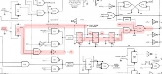
Pertec-TX8840A-9-25-Rewind-Diagram.jpg

In order to better understand the BOT detection process during the rewind, I extracted some information from the documentation. It looks like this (unless I'm mistaken):

DURING REWIND

1. BOT TAB DETECTED
2. U17A is set.
3. U18D Second single shot is triggered
4. U23A The Q output of flip-flop RW3 & NRW3 goes low
5. U38A & U38C are disabled, NRWR & NRWRD go high
6. it deactivates U51 (K2 relay driver)
7. and triggers the 0.5s single-shot U31, Q9 and associated circuitry
8. Q50, Q51, Q41, Q42 turn on for the duration of the on-sate condition of the single shot, this raise the reel servo amplifier current limits for the large deceleration required to bring the reels to a rapid halt.
9. Rewind ramp generator is disabled


By analyzing this I start to think that a relation is possible between the failure of the "taking into account of the BOT" during the Rewind and the destruction of the power transistors on the heat sink.

If U51 does not deactivate K2, the machine continues its rewind. Meanwhile, U31 single shot send the juice via Q50, Q51 to Q41, Q42, to stop the rewind. In that situation the reverse (Q43) and forward (Q42) transistors should be activated simultaneously during 1 or 2s until the tape is fully unwound.

It could also be something other than U51, this sentence jumped out at me:
"Turn on for the duration of the on-sate condition of the single shot"
What if U31 didn't do the job (no shot ? continuous shot?) This would explain that the transistors were not necessarily always destroyed when the BOT is detected during a rewind but also during normal fast successive rewind / forward operations.

Finally it may be Q50 and/or Q51 no longer work, the rewind does not stop because the power is too weak to counter the inertia of the reels but it still tries to forward while the rewind is launched at full speed ... But would that justify a breakdown of Q42? Not sure ...

How to proceed ? To limit the breadown of my power transistor maybe start to desolder and test Q50 and Q51. If they are OK, observe in full rewind if K2 is triggered when the BOT passes in front of the sensor, that would directly confirm that U38A and U51 are working or not. If K2 is triggered, try to find the culprit at the level of U31, Q9 and associated circuits. Now for this a small problem : no Q9 in the schematics and diagram, it's just mentioned in the text of the manual (Inconsistencies in documentation due to multiple board revisions?)

I also have a hypothesis for the origin of the failure, or at least the explanation of the premature wear of components normally reliable over time but maybe currently under stress:

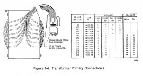
In the documentation they mention a Transformer Plug Assembly

Pertec-TX8840A-9-25-Transformer-plus-assembly.jpg
I checked this and without surprise I discovered a plug made for a configuration with a primary at 220V, but here (Belgium) it's 240V for decades.

Well, any help is welcome, in the meantime I will continue to check why the detection of the BOT during the rewind does not cause the reels to stop.
 
LAST NEWS :

- With a lot of attention I observed the relay K2 during a rewind, no reaction when the BOT passes in front of the sensor.
- I managed to start a bootable tape in a cold start mode on my DCC-116 (Clone of DG Nova 1200), after the complete loading of the OS, the computer initiates an automatic rewind (by software or EOT), this was enough to instantly burn out the transistor used for the Take Up Reel forward, namely good old fellow Q42.

So about the death of Q42, it's not just a question of the passage of the BOT in front of the sensor during the rewind, but of the simple fact of initiating a rewind. Or maybe more specifically: to initiate a rewind during a forward, the transition between forward and rewind, a short time when Q42 and Q43 are maybe used at the same time.

I also want to add that the tape drive did a lot of low speed forward / rewind during the loading which it did not do before the failure. With most magnetic tapes, after a certain number of retries, the computer or the Pertec simply stops reading and stops the loading process.
I wonder about the possible imprecision of the transistors which control those dedicated to power.

Also I think I will replace without going into detail:
Q39, Q40, Q45, Q46, as well as Q50 and Q51.
On the Heatsink the only ones that I haven't replaced yet are:
Q57 (-10v) and Q32, Q33 (capstan servo amplifier reverse and forward), I think I will also replace them.

But what is the common point between the absence of reaction of K2 during a rewind, the death of Q42 because of a rewind during a forward, and the imprecision during the reading of the data?

That's the question
 
Back
Top