• Please review our updated Terms and Rules here

Xerox 6060 keyboard/ olivetti M24

Seanbar

Member
Joined
Feb 16, 2019
Messages
14
Location
columbia MD U.S.A
I just aquired a Xerox 6060 keyboard. It's a rebranded version of the olivetti m24. I am trying to hook it up to an at&t 6300, which is also a rebranded olivetti m24. It has a few missing keys, but relitively it's in good shape. However, the seller failed to mention in pictures or writing that the cord had been severed. So now I'm trying to recreate the proper db9 cable for the keyboard.

I have looked at pinouts and know how it's supposed to be setup, however, they prove quite useless when the cable has been cut. I'm not a keyboard expert so trying to determine which wire is for data, clock,+12 v, and the 2 for ground is a bit confusing.

What I do know is that 3 wires lead to the voltage regulator UA7805csp. A schematic can be found here.

https://www.datasheetarchive.com/pd...fc2b634dae9eb714d9cda0c&type=M&term=UA7805CSP

2 wires lead to it's ground pin and one leads to one what I believe is it's input lead?? So I'm guessing those take care of the 2 ground and +12v? Or could I have that wrong?

The other two wires lead to a chip labled ON74LS5N and 8636CR. One wire leads to it's bottom 3rd pin and the other leads to it's bottom first. So I'm taking it that one of these wires are for data and the other is for clock, but again I'm not sure and I don't want to destroy this keyboard so I'm hoping to get some help so I can make this keyboard fully functional again

Any help would be appreciated!

Thanks!
 
I think you need to take a closer look at the first chip that you mentioned. You're missing a digit or two.

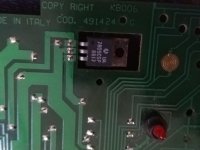
Sorry it's UA7805csp 8617. I cut it down in my search because it only came up with results in a different language.
IMG_20190411_095928.jpg

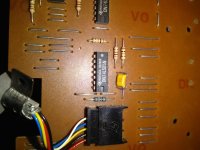
The other chip is more of a mystery to me IMG_20190410_212328.jpg

I couldn't find a schematic of this chip at all. I searched with 0s as well as Os interchangeably.

Any ideas?
 
Sorry. Here let me post a picture of both of them so you can get a better idea.

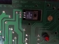
This is the first one. That the first three wires are connected to.
IMG_20190411_095928.jpg

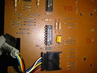
This is the other one.
IMG_20190410_212328.jpg

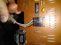
This is where the cord connected into
IMG_20190411_095740.jpg

Let me know if this helps clarify.

Thanks!
 
The ICs will have a mark, dimple, notch or some such indication as to the orientation of the pins. Place the IC so that the indicated end is up, looking at the top of the IC. the upper left will be pin one. The pins are numbered around counter clockwise. 1 through 14 or more depending on the size of the chip. Please give us the wire and the connected pin number.
Dwight
 
Oh well, don't bother figuring out the correct wiring, I guess it's not exaclty a beginner task (I did reverse engineer the keyboard connector of a Tek Terminal, but I have spent a bit of years reparing/troubleshooting).
I'll try to map the wire colors to the DB-9 pins on my M24 keyboard later today if nothing bad happens.

Frank IZ8DWF
 
Here it is:

1 Red
2 Black
3 Yellow
4 Blue
5 White
6,7,8,9 NC

I double checked, but if something goes wrong, don't blame me. Yellow and Blue go to the same trace on the keyboard PCB anyway.

Frank IZ8DWF
 
Without telling use what pins the wires go, we won't be able to help much. If the clock and data pins are swapped, it won't work but won't do any harm. If the +12V goes to any of the wrong locations it will damage stuff. If the ground leads are both swapped with the signal leads, it may damage the computer or the keyboard. You should at lead verify that the grounds and +12v go to the right place.
Dwight

Well, of course pin numbers are on the DE-9 male connector that's the standard for this keyboard. It was understood that the OP wanted to solder a new connector to the wires.

Frank IZ8DWF
 
Without telling use what pins the wires go, we won't be able to help much. If the clock and data pins are swapped, it won't work but won't do any harm. If the +12V goes to any of the wrong locations it will damage stuff. If the ground leads are both swapped with the signal leads, it may damage the computer or the keyboard. You should at lead verify that the grounds and +12v go to the right place.
Dwight

Hey sorry. Phone died last night and I'm at work right now. Will be getting off late afternoon and can tell you the right continuity for the leads. Yeah i kind of figured on just waiting until it was figured out to test anything.

I have my notes for continuity scribbled down on a paper in my car. In the meantime I found continuity on another chip which is pictured below.

View attachment 52383

I know that both pin 20 as well as 27 have continuity on this chip. If I am going counter clockwise from the notch at the top left.

Frank, I noticed that about the yellow and blue when I was doing continuity as well. I'm hessitently guessing that these are my ground wires since there are 2 grounds, but I'll try to Sneak away and give you more information as soon as I can.
 
You attachment didn't work. I'm assuming your pins 20 and 27 are in the computer and not the keyboard. When asking for the pins, I meant the ICs pin numbers in the keyboard. I suspect that the wires that go to the 74LS05 are the clock and data. These are typically driven by open collector pins. Still, without knowing which IC pins they go to, I can not assure you that they are.
The colors of the wires may not be a good determination of what one manufacture used them for compare to another.
I don't have the Olivetti schematic handy but I guess I'll need to dig it up off the web.
Dwight

fwiw, both keyboards (mine and the OP's one) are made in Italy by Olivetti and are meant for the same PC (or same clones). I wouldn't compare it with another random keyboard, would you? Still wire colors could change from one lot to the other, but he can easily determine if yellow and blue go to GND like on mine, then if the white goes to the input of the 7805. However, he asked for colors to DE-9 pins, and that's what I traced on mine. If he could reverse engineer the correct pinout alone, he wouldn't probably bother asking here.

Frank
 
If the +12V going into the 7805 is on the correct pin and the grounds are properly connected, there is little issue with the data and clock pins being swapped. My response was just that the original question I ask wasn't answered. It may have been my fault for not making the question clear enough.
Dwight
 
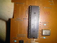
Hey guys. So the attachment was for a chip in the keyboard. It's an NEC chip
IMG_20190411_200001.jpg

Just in case the attachment doesn't work this time, it's a NEC 8634P8. Other codes read as such: D8049H0604 and CSPS.

The following is the continuity I was able to make out for the wiring.

Red: pin 1 and 10 on the 74LSo5

Black: pin 3 on the 74LSO5 and pin 6 on the NEC chip

Yellow: middle pin of the ua7805 listed in the schematics i posted as ground, pin 7 on 74LSo5, and Pins 7 20 and 27 on the NEC chip

Blue: the same as yellow

White: I think on pin 1 of the ua7805 chip which is listed as input voltage.

So I'm not sure but this is my hunch at least

White is for 12+v
Yellow and blue are for ground since they lead to a ground pin on the ua7805 chip which is listed as a voltage regulator.

Red is for clock because it connects only to the 74LS05 and helps regulate data.

And black is for the actual data.

But again this is a first for me so I could have that all wrong.

Let me know if there's anything else that could be helpful

Thanks!
 
Hi everyone!
Thanks again for your help with figuring out the keyboard wireing. A few weeks ago I went ahead and just went for it, soldered it all together and plugged it in. The leds on the keyboard lit up. But then nothing. So I went ahead and flipped the red and black wires, and it worked! So the final wiring is as listed:

White for 12 volt
Yellow and blue for ground
Red for data
Black for clock


Thanks again!
 
Back
Top