• Please review our updated Terms and Rules here

non standard electrolytic capacitor values

VERAULT

Veteran Member
Joined
Jan 30, 2012
Messages
8,539
Location
Connecticut, USA
So I am attempting a recap of a macintosh LC psu. The problem with these tiny things is they have strange value capacitors. Some of the values I need to replace are 270uF, 56uf, and 8.2uf. All the voltages are 50V and below, these are small caps, sans the largest which is rated 180uf 385wv (What does the WV designation mean?),

Any ideas where I can find these or how to proceed?

20171201_135515.jpg.866fe7f8fe0426c5b31705853bc21bd1.jpg
 
Actually, most of those capacitance values are pretty standard. You may have to go up a bit on the voltage rating (WV = working volts); e.g. 180 µF at 450V aren't uncommon at all. Just verify physical size match. The 1000µF at 10V may have to be replaced by 16V caps, but that's no big deal.

Just use a reputable brand.
 
You might also look at the tolerances of electrolytic capacitors. It might surprise you.
Also, why are you replacing all the capacitors? Is there a problem with the supply and what is the cause that would require replacing all the capacitors?
Dwight
 
You might also look at the tolerances of electrolytic capacitors. It might surprise you.
Also, why are you replacing all the capacitors? Is there a problem with the supply and what is the cause that would require replacing all the capacitors?
Dwight

The LC "brick" PSUs are notorious for having leaky secondary caps. The rubber plugs in the bottom dry rot and shrink, letting electrolyte seep out the bottom. I've recapped a few so far.

Unfortunately, the 180uF 385WV "pancake" line cap is basically unobtanium. A potential substitute is this:

https://www.mouser.com/ProductDetai...=sGAEpiMZZMvwFf0viD3Y3TIkHbBp2i90WLsKS/tiekk=

It has the same farad rating and a slightly higher working voltage. The issue is size, the internals of the PSU are basically moulded to the size of the existing capacitor. I don't remember the exact dimensions, but there is basically zero room both height and circumference wise. Fortunately, the line cap never seems to be bad in the units I've recapped.

The only other oddball is the 8.2 uF 50v cap, which can be a bit difficult to find, but it is available. I use this one:

https://www.mouser.com/ProductDetail/710-860160672008
 
Yes, they all leak. Had to do the same with my 475 PSU just a few months ago and the leakage already caused severe damage on the bottom side of the pcb. I had no issues finding replacement caps - in Germany at least. For some, I didn't even bother and used ones close to the original ones, e.g. 10uF for the 8.2 uF one, since I had these already. With tolerances >20% it's not much of an issue.
 
You might also look at the tolerances of electrolytic capacitors. It might surprise you.
Also, why are you replacing all the capacitors? Is there a problem with the supply and what is the cause that would require replacing all the capacitors?
Dwight

They all have what looks like crusty black coffee under them and the smell of rancid coolant. Just about all of them except for the large 180uf cap are leaking and I want to repair the board before its too corroded to do so.

Unfortunately, the 180uF 385WV "pancake" line cap is basically unobtanium.
So the size of the old cap is the limiting factor? Apple,,, man they made some bad choices.
 
Thanks guys, Ill buy enough of the main caps to rebuild four of the 6 psus I need to fix. Chuck ill take a look at those 220uf caps. Is tha variance from 180uf still ok?
 
Just move to the next standard value above the labelled uF value, and use the same voltage rating or one step above is ok within limits of the physical size. The 270uF 10V cap has a dome top, it has likely dried out and gas pressurized. You could replace that with a 330uF 16V for one example. Go for 105 deg C rated electrolytics, rather than 85 deg C if you can get them.

If I were you I would replace the diode CR4 too, which has been significantly thermally stressed.

By far and away the superior electrolytics made on this planet (in this time) are Japanese. So go for Panasonic or Nichicon.

Sometimes it looks like an electrolytic capacitor might have leaked(physically) though sometimes they were stuck to the pcb with a horrible brown contact adhesive.

In any case if they have leaked there is an easy way to find out. It makes the rubber bung on the base conductive, so if you push the DVM's meter probes onto the rubber bung and you measure any resistance at all, they have leaked in the past and if that is the case a cleanup and inspection of the area is required.

oh no they certainly leaked.. this isn't that gluey material to which I know what you are talking about. Its actually very wet and smelly. I currently have 6 Macintosh LC's left in my collection (various from model I to Model III) All have the same PSU and only one currently is working unaltered. The rest are ALL leaky and they came from two different sources. I think its just a particularly poor design.
 
Last edited:
There's no need to substitute any of the secondary caps for other values, they're all still very common values and sizes. The only oddball is the primary line cap, and they're less likely to be bad.

If you have one of those cheap capacitor testers, throw the line cap on it and check it. If the farad rating is in spec and it has less than 5-10 ohms of ESR, it's fine.

Im usually in agreement with you. Id say 90% of the primary line caps I come across are still within spec. But since ALL the rest were leaking, and this one actually was bulging ever so slightly.
 
Most of the fat line capacitors I deal with are slightly domed due to the warping when the relief vent is stamped in the crown. The dome could be a sign of failure, but it can also be normal. The last two LC style PSUs I recapped had slightly domed tops, but tested fine after several power and load cycles. Not to say yours can't be bad, that's what capacitor testers are for.

The large majority of bad line capacitors I've encountered showed no outward signs of failure at all. They just went to ridiculously high ESR values and had no capacitance left, or shorted out, which often causes the primary switching circuitry to go bonkers and make clicking noises.

Here's one PSU I had where both line caps went bad. One showed up as a diac and the other with like 1k+ ESR and 10nF capacitance. Both were supposed to be I think 220uF at 250v.

https://www.youtube.com/watch?v=lgwUadgIM8k

The PSU still powered up, but it would fall flat on its face and cut out with any appreciable load applied. Like the internal fan still ran, but it would die if a hard drive was plugged in.
 
Caps that have fairly high heat dissipation (due mostly to ESR effects-ripple current) usually dry out and turn to empty cans rather than short out. Nominal working life on these is 10 years.
 
Last edited:
So I bought all the caps from mouser and they are listed below if interested (ones left out I already had in my inventory).
http://www.mouser.com/ProductDetail...mDNgx1uK8/A==&countrycode=US&currencycode=USD
http://www.mouser.com/ProductDetail...Sg6rX7oMz0g==&countrycode=US&currencycode=USD
http://www.mouser.com/ProductDetail...C6%2bGA5Zeg==&countrycode=US&currencycode=USD

The large single cap has been a point of contention in that finding the correct value in such a short and stubby size to fit in the psu case is pretty difficult. I ended up buying these as they are the shortest i can find at 25MM :
http://www.mouser.com/ProductDetail...inuxkT3hj8Q==&countrycode=US&currencycode=USD

In the end they are taller in that (due to them being wider than the original, we will get to that.
So I have done two psus already and they work. I started off doing the worst one first. IT was severely rusty and the PCB was very corroded due to the cap leakage and whatever else rusted the psu case. The traces seemed ok enough to warrant the repair.

First off the unit works now and outputs good power, however the PSU (not the internal speaker) is outputting alot of audible whine. This may be due to grounding as the metal case is still soaking in vinegar until I can de-rust and paint it. Im using an alligator clip to work as ground for now. So like I said the unit outputs good power but there is whine. I will update on that when I finish restoring the psu case.

The second unit is much like the rest in my pile. The caps have all leaked and the bottom side of the pcb (low voltage side) shows corrosion on the solder and traces from cap leakage, but nothing terrible.)
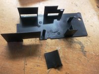
So I put the unit back together in the case. I had to use flush cutters to cut the semi-cylindrical tabs of the plastic insultation trays because the new cap is wider.
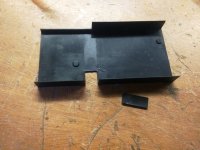
20201101_132340.jpg20201101_132010.jpg
I then put the the plastic trays in the metal case and put the PSU back together. The 5 machine screws all go back in with just a bit of coaxing. Driving the screws in will bring the case back together again. As seen here is looks fine, there is only the slightest area towards the back where only one lone screw holds the case together that shows bulging.
The psu works and there is no shorting and no evidence anything is too tight and may wear over time.

Now going back to what I said about the cap ending up being more than 25mm. I didnt take into account the new caps's width which is just wide enough to warrant the previous tabs to be removed as well as it encroaching upon a few components nearby. The cap ends up hanging over slighly some components circles in read here: 20171201_135515.jpg.866fe7f8fe0426c5b31705853bc21bd1.jpg
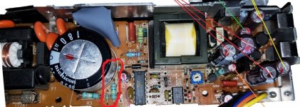
I cut a square of large heatshrink material to place under the cap to insulate it from these components.
In the end this raised the height 2 or 3 mm.
End the end it worked out. Im sure there are caps that would fit better but I am ok with these.
 

Attachments

  • 20201101_133214.jpg
    20201101_133214.jpg
    196.6 KB · Views: 1
  • 20201101_133209.jpg
    20201101_133209.jpg
    179 KB · Views: 1
Back
Top