• Please review our updated Terms and Rules here

8 bit ISA Sound Blaster clone identification, jumper pos, driver help.

Haunter_1

Member
Joined
Mar 26, 2021
Messages
19
Location
Northeast Pennsylvania, USA.
Hello Everyone,

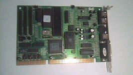
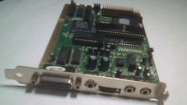
I recently purchased a seemingly rare Sound Blaster clone and would like to know if anyone has any information on it, or if there are any particular SB driver versions and jumper positions that would allow me to test it for functionality on my IBM XT. The attached pictures are small and were provided by the seller, but they do match the card I recieved.
1107-2010-CT-1336A-8-bit-ISA-Sound-Card-Stereo.jpgSBC2.jpgSBC3.jpgSBC4.jpg

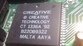
It appears to be an 8-bit card, with the 16-bit ISA bus being used only for the CD-ROM function. It has a CT 1336a chip, and has an 8031 cpu. The seller referred to it as SB Pro 2, however when I attempted to install SB drivers the card was detected as a Sound Blaster 2.0.

I don't plan to use it for games, but it would be nice to test it on my XT. It has a lot of jumpers which I believe to be a good thing, however I am not sure whether or not the scheme matches any of the SB cards. I am still very new to pre Pentium/windows machines and any help would be greatly appreciated.

My IBM specs are as follows:
IBM 5155 XT
640k Memory
CGA Graphics (7.5" MC only + composite monitor)
Blue Lava Sys XTIDE-CF
64mb CF HDD
Dual 5.25" 360kb FDs
PC-Dos 4.01
NEC P2 Parallel printer
 
Hello Everyone,

I recently purchased a seemingly rare Sound Blaster clone and would like to know if anyone has any information on it, or if there are any particular SB driver versions and jumper positions that would allow me to test it for functionality on my IBM XT. The attached pictures are small and were provided by the seller, but they do match the card I recieved.

View attachment 67448View attachment 67449View attachment 67450View attachment 67451

It appears to be an 8-bit card, with the 16-bit ISA bus being used only for the CD-ROM function. It has a CT 1336a chip, and has an 8031 cpu. The seller referred to it as SB Pro 2, however when I attempted to install SB drivers the card was detected as a Sound Blaster 2.0.

I don't plan to use it for games, but it would be nice to test it on my XT. It has a lot of jumpers which I believe to be a good thing, however I am not sure whether or not the scheme matches any of the SB cards. I am still very new to pre Pentium/windows machines and any help would be greatly appreciated.

My IBM specs are as follows:
IBM 5155 XT
640k Memory
CGA Graphics (7.5" MC only + composite monitor)
Blue Lava Sys XTIDE-CF
64mb CF HDD
Dual 5.25" 360kb FDs
PC-Dos 4.01
NEC P2 Parallel printer

I doubt that it's a clone - most probably an OEM version. I not sure, but I don't think Creative let that chip go out in the wild. The only reversed engineered clone I can recall is the Snark Barker. There's plenty of info on the that chip over on Vogons.
 
I doubt that it's a clone - most probably an OEM version. I not sure, but I don't think Creative let that chip go out in the wild. The only reversed engineered clone I can recall is the Snark Barker. There's plenty of info on the that chip over on Vogons.

Thanks for the tip about Vogons, I will check it out. I definitely agree now that it is most likely an oem product. It seems to be very well made and has a lot of features including support for Sony, Mitsumi, and Panasonic drives.
 
The CT1336A chip on it is a Soundblaster 2.0 part, so it is almost certainly a "genuine" OEM product. There's no silk-screening on the board anywhere with a "CT-xxxx" model number? (Or an FCC ID, or anything?)

Back in the long-ago I used to have a Soundblaster 16 OEM that had multiple interfaces for both IDE and proprietary-interface CD-ROM drives, but I've never seen a triple-interface 8-bit Soundblaster before. Maybe it was a really late low-end entry built to use up leftover chips.

Thanks for the reply Eudimorphodon,

I looked everywhere on the silk screening, but the only part number I could find is on the bottom of the board. "9433" then "1107-2010". Possibly just internal manufacturing, inventory or configuration codes? I'm considering that maybe there was a printed label which fell off.

The dates on the chips are all over the place too, which definitely makes me think either it was a last run of whatever parts were in the warehouse, or perhaps a prototype which I would only consider due to the lack of a copyright on the board.


https://www.dropbox.com/sh/2zd4zfhzznsdju1/AABDtFClPi2oincrWtEeCcm0a?dl=0
 
"9433" is a date code. Week 33 of 1994, so sometime in the middle of August 1994. The 74 series logic chips have date codes earlier in 1994, so it'd be accurate.

That 1983 2732 EPROM is weird, as is that 1980 LM8031, which is a very early microcontroller. I'd guess whoever made the card found a stock of old chips for cheap and used them.

You might consider getting the EPROM dumped to save yourself headache in the future if it goes bad. The sticker covering the window is damaged, you may want to cover it up with electrical tape.

That is great information. The EPROM chip socket also has 4 empty pin slots which is also curious. I will cover the window with some black clean room tape (try this stuff) as per your recommendation.

I am still yet to get any sound out of it as I am still trying to decipher the jumper settings. JP-2,3,4 are for the CD I/O address (not used) which is currently set to 300-303. Jumpers JP5 "game en" is closed, JP6 "24" is open, and JP7 "22" is closed. I don't know if "22" means address 220, or if it is for something else. When I ran TEST_SBC.exe it did not give me an error when it looked at address 220, but there was no sound.

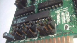
The other jumpers are also a bit confusing compared to a normal SB. It has jumper blocks for data request, data acknowledge, and interrupt, but there are no instructions printed. As pictured It looks to me as if it is set IRQ5, with Data request at DRQ1 and data acknowledge at DACK1. I tried changing to what I think is Interrupt 7, but still no sound from TEST_SBC. I do not know if the jumper should be between the center and the top pins, or the bottom pins, and I am still trying to figure out the function of JPs 9,10,11. I could map the traces on the board but this would be very slow indeed.

There is also a closed "LPF" jumper which I am assuming is for low pass filter, and an SP jumper which is open.
 
Update on interrupt jumper field JP11.

It appears that the central pins, and the numbers above the field, correspond to the ISA pins for there respective interrupts. the right most Interrupt 10 seems to be for the CD-Rom and traces to the other bus. The top pins are all common to the collector of Transistor Q4 located near the CD-rom I/Os. The bottom pins except for the one under "10" all trace to a pin on the 1336a which I assume is the interrupt output signal.

It seems to me that the interrupt signal for the CD-ROM comes from the transistor and may be connected to any of the 4 interrupt lines with 10 being default by jumping top to center pins, and the 1336a interrupt signals can go to interrupts 2,5, and 7 by jumping pins bottom to center.

The situation is probably the same for the DMA jumper fields, but I will be checking to make sure.
 
Back
Top