• Please review our updated Terms and Rules here

I'm after some SMD Soldering/desoldering tips

Bworp

Member
Joined
Apr 23, 2019
Messages
33
Location
Tasmania, Australia
I have done very little SMD work previously, and could use some advice on replacing some VRAM chips.
I recently picked up a Compaq Deskpro 4/66i which was really messy, but despite the dusty crud inside and the rust on the bottom of the case, it works *nearly* perfectly.
On first boot it worked fine initially, but displayed more and more artifacts and weird colours the longer I left it on.
Next time I tried booting it, I only got a blinking cursor and some error beeps to tell me there was a video problem.
Sounds like the VRAM to me, but what do you think?

This motherboard does allow me to use another video card and disable the on-board, so it's not the end of the world, but it would be nice to get it fully working, not to mention good experience for me.

Anyway, I think I can source the correct chips, but it will be a fiddly pain-in-the-butt job to replace them, so I'd like to know what I'm doing before I get started.
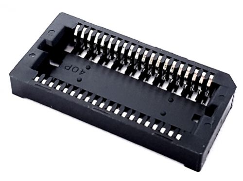
See, the pitch of the legs is small (1.25 pitch I think you call it?), and I think the ICs themselves are designed to be through-hole; it looks like the legs have been bent underneath the ICs to attach them SMD fashion to the pad.
Here is a picture:


My current plan is to get four replacements, then desolder the existing chips one by one and replace them until the computer works. Of course this will involve bending up to 160 tiny pins without breaking them, a lot of very careful alignment, worrying I'm going to lift pads, hoping I don't get any solder bridges especially underneath the chips where I can't easily see or get to them, etc.
Then I just have to hope that it was the RAM chips and not the controller that were dead, and that the replacements I get are all in working order too.


As you can see, for a novice this is a bit of a daunting job, so any advice would be greatly appreciated.
 
That will not be a job for the faint of heart! I'm thinking you are going to want to use hot air to remove those, and it seems like there is some low temperature solder than you can add to it that can help (chip quik maybe?). Once the old chips are off, you could use solder wick and flux to clean up the pads to remove all the old solder. They can be soldered by hand with lots of flux, but again, none of this will be an easy job.
 
try cleaning the board, then examine all of the solder connections for corrosion

I've given it a light clean already and looked over the pins. There doesn't seem to be any obvious corrosion, but I'll give it a closer look.

That will not be a job for the faint of heart! I'm thinking you are going to want to use hot air to remove those, and it seems like there is some low temperature solder than you can add to it that can help (chip quik maybe?). Once the old chips are off, you could use solder wick and flux to clean up the pads to remove all the old solder. They can be soldered by hand with lots of flux, but again, none of this will be an easy job.

Hot air makes me nervous, but I'll use it if I have to. I've never used it to desolder - it feels a bit too imprecise, and I'm worried it will damage the board or undo nearby solder. Is that something I should be worried about? Thanks for the tip about chip quik though! My local electronics store sells it, so I'll definitely give that a shot.

Also, I've had an idea about installing the replacement chips. I was thinking about using socket strips:
PI6470-machined-pin-ic-socket-strips-32-wayImageMain-900.jpg


I wouldn't have to be so nervous when bending the legs. If they break, I'll just cut off more and try again. They should also be easier to solder, as I can get on both sides of them. And most of all, it will allow me to swap chips around and find out exactly which one is the culprit.
The only problem is I'm having trouble finding anywhere that does them in 1.25mm
Does this sound like a good idea? And does anyone know where I can get them in the right pitch?

[edit]Nevermind. Just realised I should have been looking for 1.27mm, not 1.25mm. Pretty easy to find. My question about whether this is a good idea still stands though![/edit]
 
Last edited:
Hot air can scorch a board if you aren't careful, it is best to use a preheater under the board to preheat the entire board to a temperature below the solder melting point, and then use the hot air to bring the part/joints you want above the melting point.
 
you can also buy SMD nozzles for rework stations

I needed to socket a bunch of 32 pin SMD flash proms recently and I've had great luck switching to the special Metcal tips which heat all the SMD pins simultaniously for part removal.
That's an expensive solution esp if you don't already have a Metcal
 
Just cut the legs of the old chip (as close to the chip as possible) and take your time (and space) to desolder them one by one. I can't stress this enough, be careful to not lift the pads with the legs. Depending on the board this can happen very easily.
 
The vram chips are not through-hole with the legs bent under, that package type is known as j-lead.
 
If you have kapton tape available, taping off the board around the target IC is a good way to prevent hot-air from affecting other components. You are right to be a little wary, I have definitely knocked off a cap or resistor or two that was next to a big IC.
 
Last edited:
A video of what Al's talking about. Many SMT sockets like this are actually manufactured so that the center section easily breaks away with just a little pressure.

For these large components,I find that a tiny ball of 3M "Press in Place" caulk will hold things in place and come away cleanly. I found it useful holding the tiny bits in a 2-cycle carburetor when reassembling. Doubtless there are better materials, but it's what I happen to have on hand.

s-l640.jpg
 
Last edited:
If those pins really do bend under and they are sitting on small surface pads, it precludes a common method I use removing surface mount fine pitch pin IC's ( like the large one shown in the photo) is to put thin enameled copper wire, threaded between the IC body and pins, tied off at one end an use it to pull the IC pins off the pad (when heated) This pushes the pads towards the pcb surface and they don't lift. But in this case the wire would snag on the bent round pin edges, so that method is out the window.

(I wouldn't put hot air anywhere near it). I wouldn't cut the pins either, the forces can lift the pads especially when its not through hole.

In this particular case I know of only one method that will work:

You need to get some metal plate, brass or copper, about 1.5mm thick. Fold it around into U shaped rectangle so that its free edges are the length of the IC an just slip down the sides of the pins on each side of the IC , to make a de-soldering "tool".

Get a high wattage soldering iron with at least a 1/4" dia removable tip. Cut the tip down to a slightly smaller diameter and drill a hole that size in the metal tool in the center of its flat section. Pass the tip through that hole and strike that with a hammer to rivet the tool to the end of the soldering iron tip. You now have a tool where you can melt the solder on all the IC's pins simultaneously.

Then before you start add fresh solder on all the IC pins down both sides of the IC, place the tool over it, wait for the solder to melt on all pins, and then some gentle sideways pressure to free the IC, then clean up the pcb with wick & IPA.
 
I just powder some Cerrobend 158, pack it around the pins and heat the board with a incandescent 150 watt PAR 38 lamp. Clean with a toothbrush. I've done this with soldered-in PLCC EEPROMs, cleaned them up, reprogrammed them, and soldered in a PLCC socket for them. Doesn't bother the surrounding components, since the final temp is less than 100C.
 
OK, some great info here. It's good to know about j-leads and that they are a thing. Also good to know there's actual sockets for them!
I'll have to do a bit of thinking to decide which method I'm going to be most comfortable with. Knowing me I'll drag my feet for a few weeks, but I'll let you all know how I go.
 
Back
Top