• Please review our updated Terms and Rules here

Compaq Deskpro 386/25M Power Supply

firebirdta84

Experienced Member
Joined
Jun 26, 2013
Messages
244
Location
Central Iowa
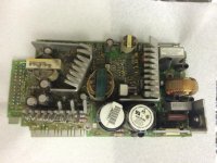
The Compaq Deskpro 386/25M that I have posted about on other threads here through the year just had a power supply failure.

Hoping I could just create a modern ATX power supply adaptation, I removed the power supply from the system and testing, only 1 of the 24-pin is providing any voltage.

However, nothing about this power supply seems standard in any way.

The pin-outs on the 24-pin connector that connects directly to the motherboard don't seem to match anything I can find online, even on the fantastic site http://pinouts.ru

Here's what I've come up with so far, mostly based on tracing the connectors on the PCB board back from the standard connectors for peripherals and hard drives.
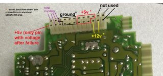
Pinout.jpg
(hi-res picture at http://bit.ly/1kX6BJh )
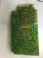
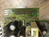
IMG_3266.jpgIMG_3260.jpgIMG_3259.jpg
hi-res pictures at
http://bit.ly/1q1XqpY
http://bit.ly/1vkJtoS
http://bit.ly/1rnCdKV

Please see my Google Drive-hosted pictures of the power supply here, as well as some links to relevant but unhelpful search results.

http://bit.ly/1z4xqw4

I tried making my own adapter from a modern ATX power supply already, just leaving unconnected the connectors I mark in purple as "mystery", but I get no video-out or boot sequence from the motherboard.

I find it worthy to mention that the one pin I identify as +5v and the "only pin with voltage after failure" causes some LEDs on the motherboard to light up, and without it, the motherboard is dead, even with the known +5v and +12v pins connected to a modern ATX power supply.

The board says

Board No. 002021-001
Diagram No. 002020
Spare No. 129069-001

All Google searches turn up only ancient parts-house listings for way-overpriced hardware. All pinout searches seem to direct to 24-pin connectors that can't possibly be right, based on my tracing the PCB connections to known standard peripheral connectors.

The power supply is under the fan shown in the lower right of this overview of the 386 PC:
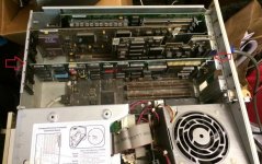
ARchive Board Installed & Pointed.jpg
http://bit.ly/1nd35Gb

Thanks everyone,

-AJ
 
Last edited:
In what way did it fail ?, Something go pop ?, How have you tested the PSU, with and without Motherboard connected, Is that the one with green and red LED's ?.
 
Good luck with that--both Compaq and HP made gear with oddball power supplies. I've got a very beefy PSU from an unknown Compaq workstation--has a 24-pin connector just like an ATX unit, but it's not ATX. I haven't the faintest idea of what to do with it.
 
Yes very oddball as i remember, I'm sure i got a couple from a 386 somewhere hiding in the shed, IIRC they have long connectors and all white wires.
 
Malc,

Thanks for asking the question on the specifics. I would call this a "silent fail". There was no pop. One day the machine was working perfectly when I powered it down, and a few weeks later when I tried to power the machine on again, all I got were 2 green lights. one green LED on the motherboard itself, and the green power light on the front of the face of the machine. No sound. No video signal. No fan. No hard drive spin.

That is when I removed the power supply and tested.

I did move the computer into a new building between the last successful use and the failure, and the first power on in the new location is when I realized the "silent failure". So that may or may not have been a factor, but the timing indicates that it should be considered as a factor. When I think of static, I think of it affecting more sensitive chips, but not power supplies. Could static have caused a power supply regulator fail or something like that? I'm only guessing, because I have no experience here.

As far as testing the PSU: I removed the unit from the computer.
I visually inspected the board, found no components which appeared blown out or dark or otherwise unusual to me.
Then I visually determined which pins were ground by looking at the circuit board lands/connections.
Then I connected 110v to the input leads using a custom-built cord.
Then I tested all output leads against ground, and determined that only one pin produced any voltage, the +5v one on the end shown on my diagram in red with the note about this.

So only the one pin shown in my diagram is the one producing +5v, all other pins are dead.

And the machine has only 2 green and one yellow LED. The yellow is for hard drive activity, and it is off. The 2 green (power on front and green on motherboard itself) are lit sold on power-up. Testing my ATX power supply adapter has shown that applying +5v to this single pin that was the only one working on failure causes these 2 LEDs to light up.

The system does not have any red LEDs. Any you see in the picture are from an Archive tape controller ISA board, which I removed prior to this failure.

---------

Chuck(G), does the "beefy" power supply you mention resemble the pictures I show in my post of my power supply? If so, you might be able to help me with pinout voltages. Even if not, do the voltages match at least the "known" voltages I show in my diagram? If so, just knowing what the rest of the voltages are could help.

Thanks for the discussion, everyone!

-AJ
 
Last edited:
Nope, sorry, when I mean "beefy", I also mean "big"--it's a WTX-size PSU. Went to an EVO W6000. P/N is WTX460-3505.

Thus far, nothing seems to come up for the PSU pinout.
 
I found 1 PSU but it's nowt like yours It has 1 straight 15 pin connector and all the wires are white, I'll look again later for the other one. Are you able to test the caps.
 
Malc & Chuck(G),

Thank you both for checking your stash of PSUs. You are both very kind to do so for me.

Malc,

Thank you especially for your in-depth questions and extra help with this. Yes, I believe I am able to test the caps, although I have never done it before. I'm on a big learning journey here.

Are we talking about just the large ones, or everyone on the board, including the small ceramic caps as well? And, do you think that I need to remove each one from the board prior to testing?

I have an Extec MiniTec 26 multimeter that has a capacitance testing feature, and can remove the caps and use that as a tester, unless you have another process you could point me to.

Thanks again for all your help!
-AJ
 
Don't get your hopes up too much :), There is a quicker way of testing but i'm not going there, First i'd give the board a good clean off and check for cold / bad solder joints and broken tracks, Use a magnifying glass. You're better off removing the caps from the board, I'd start with the 2 big caps looking at the pic it looks like 250v 820uf each, Make sure you know what way round they go as they are polarized, One side of each cap has markings down the side denoting the negative side. When testing caps you really need to test the ESR but you need a dedicated cap tester for that, I've used my DMM to test caps and it's not fool proof but it's gotten me out of trouble many times, Test those 2 and see what the readings are. Also ( I'm looking at IMG_3260.JPG ) To the right of those big caps there is a Red'ish cap pull that one and check, It should be non-polarized and have the values on the cap.

Edit: I should also mention before you test the big caps put your meter on DC volts and make sure the caps are not charged, ie: negative lead to negative side of cap and positive lead to positive side of cap.
 
Last edited:
Malc,

Thanks so much for your assistance here.

I am going to take a slow and methodical approach to follow your advice here, so I will work on this in small chunks of time over the next week or so, and then check back in here.

I'm learning a lot here, so thanks to you and all for chiming in on this.

Thanks,
-AJ
 
Back
Top