• Please review our updated Terms and Rules here

SuperPET Not Working - Suggestions?

Joined
Dec 26, 2009
Messages
41
Location
Kelowna, BC, Canada
The good news: A friend gave me a SuperPET!
The bad news: It's not working. When I plug it in and turn it on it does nothing. No chirp, no whine from the monitor, no display from the monitor, no nothing.

It's the single daughterboard version and in very nice shape. I checked for burst caps and bad connections - everything looked good. I checked all of the connectors and socketed chips - they all looked fine. I disconnected and reconnected the connectors and pulled out and put back in the socketed chips and tried turning it on again. Still no dice.

I then checked is the transformer. I am getting power from it and the voltages seem close enough. Here's what I got:

4-6 17.2VAC
4-5 8.6VAC
5-6 8.6VAC
7-8 16.2VAC
9-11 21.1VAC

There are two things that looks slightly amiss, but I'm not sure if they are a problem or not. On the motherboard, I have chips in UA3 and UD7 but not in UD11 or UD12. On the daughterboard, I have a chip in U49 but none in U48, U47 (where, oddly, the socket is red), U46 or U45. Also, there is a red wire and a black wire hanging down from the bottom of the keyboard. In pictures it looks like both are connected at both ends, but in my machine one end of each wire is free.

I'd very much appreciate some suggestions as to what I should check next. Thanks!

- Rick
Hi Rick welcome to the forum! and congratulations on bagging a SuperPet!

Regarding UA3 and UD7 do you have chips in UD6,UD8,UD9 and UD10?

If you could post a few pictures of the boards it would help in checking all components are there and in the right locations.

You could look over these pictures on BillDeg's site.

http://vintagecomputer.net/commodore/superpet/

With U47 & U48 missing it sounds like you may have missing ROM's
 
I do have chips in UD6, UD8, UD9 and UD10. They are all soldered to the motherboard - no sockets.

Here are some pictures:
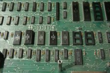
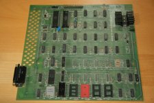
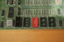
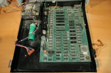
SuperPET Motherboard.jpgSuperPET Motherboard Closeup.jpgSuperPET Daughterboard.jpgSuperPET Daughterboard Closeup.jpg

These are the motherboard, a closeup of the motherboard showing the sockets, the daughterboard, and the daughterboard showing the sockets.

The pictures on BillDeg's site (plus others that I have seen) do indeed have chips in U47 and U48, which I don't. I was thinking that those chips would be for the 6809, though, and I should be able to run the 6502 without them. What do you think?

- Rick
 
Rick,

You have measured the AC voltages from the transformer - what about the DC voltages on the motherboard from the regulators?

If you pop a 6502 CPU into the vacated 40 pin socket - do you get a 'bog standard' 8032 working PET or not?

Dave
 
If I remember correctly if you take out the 6502 from the daughter board and put it in the mainboard in place of the ribbon cable and try and run the SuperPet as a standard pet to begin with.

I would then check for a clock on the 6502 and check voltages to it and the various RAM chips etc.

Your motherboard looks like the chips are all there but the daughter board looks like they are missing a couple.

That should keep you busy for starters.

Dave you beat me to it!
 
I tried removing the 6502 from the daughterboard and plugging it into the motherboard. No change, unfortunately.

> what about the DC voltages on the motherboard from the regulators?
> I would then check for a clock on the 6502 and check voltages to it and the various RAM chips etc.

These are a bit beyond my understanding. I can use a multimeter if I know where to put the probes, but I don't know exactly where to check the DC voltages, or how to check for a clock on the 6502. Could you point me to specific places to check or is there some documentation which tells me this?

Thanks for all your help - I appreciate it!

- Rick
 
I was thinking that those chips would be for the 6809, though, and I should be able to run the 6502 without them. What do you think?

Yes, from looking at the documention from zimmers, and sheet 2 of parts list, you need three ROMs (Commodore 2364) as follows:
U47 970018-12
U48 970019-12
U49 970020-12

I think a compatible EPROM is the old Motorola 68764 which may be available on ebay. Or use the 2764 with adapter.

I don't have a SuperPet but if I did, I would remove the 40 pin CPU cable from the main board, and plug a 6502 directly in the main board and get the 8032 working first. Others here with Supers may have ideas about how much of the super board needs to be unplugged, power, etc.

Let us know what type of test equipment you have, meter, scope, logic analyzer.
 
I tried removing the 6502 from the daughterboard and plugging it into the motherboard. No change, unfortunately.

> what about the DC voltages on the motherboard from the regulators?
> I would then check for a clock on the 6502 and check voltages to it and the various RAM chips etc.

These are a bit beyond my understanding. I can use a multimeter if I know where to put the probes, but I don't know exactly where to check the DC voltages, or how to check for a clock on the 6502. Could you point me to specific places to check or is there some documentation which tells me this?

Thanks for all your help - I appreciate it!

- Rick

Rick if you have a multimeter you can test the voltages on the RAM chips 2114's and 4116's and the 6502.

If you google those chips you'll check on the 6502 between pin 8 and pin 21, you should get 5v. Be careful not to short out on other pins.
Pins 9 and 18 on the 2114 again 5v and on 4116's pins 1(-5v), 8(12v), 9(5v) using pin 16 as gnd
 
I think the SuperPET Parts page is referring to the multi daughterboard version of the SuperPET. It's way different than mine - it refers to parts I don't have. The only thing that seems to be similar are U47, U48, and U49 - the daughterboard ROMs. I have U49 but am missing U47 and U48. I'll have to get those ROMs at some point. Until then, I took Dave's suggestion and ditched the daughterboard and put the 6502 on the motherboard. Still doesn't work, unfortunately.

I know some about electronics, but a multimeter is my only capability right now. Scopes and analyzers are beyond me (I'm looking to take a course to learn all this).

I checked the voltage on pins 8 and 21 of the 6502 - 4.7VDC. Close enough, right? I'll see if I can get some readings on the RAM chips.

- Rick
 
I think the SuperPET Parts page is referring to the multi daughterboard version of the SuperPET. It's way different than mine - it refers to parts I don't have. The only thing that seems to be similar are U47, U48, and U49 - the daughterboard ROMs.

The list does list the six old 4K ROMs perhaps from an earlier version of your board. Somewhere along the way, they switched to three 8K ROMs. I'm sure the top assembly drawing for your dash number board would call out the correct ROMs but its not in zimmer.


I checked the voltage on pins 8 and 21 of the 6502 - 4.7VDC. Close enough, right? I'll see if I can get some readings on the RAM chips.

4.7 VDC is very marginal. Measure once with the black return probe on a ground close to the 6502 chip. It should read closer to 5.0 VDC. The spec for these chips for Vcc is 5%. Vcc should not be lower then 4.75 VDC. Also measure a new 9 Volt battery with your meter to see if its 'calibrated'. Maybe replace the battery in your meter.
 
I checked pins 9-18 on the 2114s (UC4-UC7) and they were ~5VDC. All good.

I checked pins 1-16, 8-16, and 9-16 on the 4416s (UA4-UA19) and they were ~-5VDC, ~12VDC, and ~5VDC respectively. All good.

I also figured out about the red and black wires hanging down from the keyboard - they should be soldered to the contacts on the Shift Lock key. In hindsight this seems incredibly obvious, but the wires are short and don't actually reach the contacts. I guess somebody must have cut them off and then just left them hanging. Who needs the Shift Lock key anyway? :)

I tried a couple of other things that I thought might shed some light. First, I plugged in the disk drive that I have, a 2031LP. I power up the drive first, and then the PET. When I do that, the busy light on the drive goes on for a moment. At least that means that PET is sending some kind of signal to the drive.

Second, once I had the drive and the PET on, I typed DIRECTORY and pressed enter (of course, I couldn't see anything on the screen, I just typed and hoped). I thought if the monitor was the problem then the disk would at least spin a bit. No dice - it didn't do anything.

I thought I might try to read the ROMs to make sure they are okay. I don't have anything to do that, though, I'll have to buy something.

If anyone has any other suggestions I'm all ears!

- Rick
 
When I do that, the busy light on the drive goes on for a moment. At least that means that PET is sending some kind of signal to the drive.
That means your /RESET timer is working.

Second, once I had the drive and the PET on, I typed DIRECTORY and pressed enter (of course, I couldn't see anything on the screen, I just typed and hoped). I thought if the monitor was the problem then the disk would at least spin a bit. No dice - it didn't do anything.
I don't know that you'll get different results, but in my opinion, in the time it takes to type DIRECTORY and press return, the system may have already locked up. I'd type cA[RETURN], as in c, shift-a, return. It does the same thing much quicker.
 
I thought if the monitor was the problem then the disk would at least spin a bit. No dice - it didn't do anything.

Rick, The monitor can't be tested until the PET runs long enough to initialize the 6545 CRT controller. Disconnect the J7 cable going to the monitor until you know you are getting a valid Horizontal Drive pulse train from the CRTC. This will protect the monitor. The horizontal drive is used in the video board as the switching source to generate the 10KV high voltage. You will know when the Horizontal signal is OK when you get a VDC reading around 2.4 VDC and not zero or +5 V. This means the signal is pulsing.

I thought I might try to read the ROMs to make sure they are okay. I don't have anything to do that, though, I'll have to buy something.

Are the ROMs on sockets? If so, I may have to send you a set as the new eprom/eeprom programmer gadgets cannot program the 2532 EPROM. It's old NMOS and needs 25V power to burn them. However if the ROMs are soldered, it may be just as well to to get a PETVet gadget or the one from Tynemouth Software (Great Britain) and replace the main board RAM and ROM in one swoop. A possible problem is the height of the Super board above the main board. Is there enough clearance to place a PETVet. You might have to find taller spacers for the super.
-Dave
 
Dave - I replaced the batteries in my multimeter with new ones. I then tested it on a new 9V battery. The reading on the battery was 9.47V. Is that what it should be?

KC9UDX - I tried typing cA<Return> when the machine first booted up to see if I got a reaction from the disk drive. Unfortunately, there was no reaction.

Dave - I reread the voltages on the processor and the memory chips. The 6502 was 4.87V. The four 2114s were all 4.86V. The sixteen 4116s were -5.1V (for all of them); 12.11V (except for UA12 which was 12.10V); and 4.84V (for UA4-UA12), 4.85 (for UA13-UA17), and 4.86 (for UA18 and UA19).

I will disconnect the J7 cable for my next tests.

> You will know when the Horizontal signal is OK when you get a VDC reading around 2.4 VDC and not zero or +5 V.

Where will I find this reading?

The ROMs are in sockets. Wow, if you could send me a set of ROMs that would be great.

Thanks!

- Rick
 
Last edited:
A 9V battery should always read 9V or less. It sounds like your meter is reading high, indicating your 5V supply really is too low. I think you need another meter and to replace the power supply filter capacitor, at least.

I'm confused about the 12V readings, but not having a schematic handy, I'll wait to see what Dave says.

You can read that 2.4VDC which is really an average or RMS equivalent of 5V pulses, at J7, horizontal sync pin.
 
Yes, the voltage readings are a little high except for Vcc which makes me think your +5V voltage regulator may be low. What kind of meter do you have? A voltmeter with a digital readout or an old analog VOM? Of course your regulator is supplying power for two boards on the SuperPet. Or did you disconnect power to the upper board?

The Horizontal Drive is on J7-pin5. See Sheet 10 of 8032 schematic.

You are lucky to have the ROMs on sockets. Of course it may indicate someone had problems there. Reseat the chips in the sockets for good connection by pushing down on one end and then the other. Are they all ROMs or are some of them EPROMs? I'll send you a set. Send me (dave_m) your mailing address by 'private messages' on this forum and edit out your email from your last message.
-Dave
 
I have a digital multimeter. It's this one:

https://abra-electronics.com/test-instruments/multimeters-abra-low-cost/dm-2900-abra-autorange-multimeter-dm-2900.html?sl=en

All of the readings in message #15 were with the daughterboard disconnected.

I've pulled out and reseated all the socketed chips - that was one of the first things I did.

I disconnected the J7 cable and took a reading on J7 pin 5. It was 4.87VDC.

I misunderstood your question about the ROMs. I thought you were referring to the daughterboard ROMS, which are all socketed. All of the pictures I've seen of SuperPET daughterboards have three ROMs in the five sockets - I only have one. Only U49 has a chip in it. U48, U47 (the red socket), U46 and U45 are empty. Would I be able to get the daughterboard chips off of you?

Here's a list of my daughterboard ROMs:
U49 970020-12 (socket)
U48 Empty (socket)
U47 Empty (red socket)
U46 Empty (socket)
U45 Empty (socket)

The motherboard ROMs are all soldered except for UD7, which is socketed (hmmm... why is that?). UD11 and UD12 have sockets which are empty (is that normal?). All the ones that are there are all ROMs (MOS ROMs, to be precise), not EPROMs.

Here's a list of my motherboard ROMs:
UD6 901465-22
UD7 901474-03 (socket)
UD8 901465-21
UD9 901465-20
UD10 901465-23
UD11 Empty (socket)
UD12 Empty (socket)

Is the next step to replace the filtering capacitor or should I try a better meter first?

- Rick
 
Last edited:
All of the readings in message #15 were with the daughterboard disconnected.

Then the voltage should be closer to 5.0 V. Check the input to the regulator. If it reads 8V or more and the regulator output is low, then you may need to replace the 7805 regulator.


I disconnected the J7 cable and took a reading on J7 pin 5. It was 4.87VDC.
That means the Horizontal Drive is not running probably because the 6545 CRT Controller has not been initialized. The PET is not running properly yet.

All of the pictures I've seen of SuperPET daughterboards have three ROMs in the five sockets - I only have one. Only U49 has a chip in it. U48, U47 (the red socket), U46 and U45 are empty. Would I be able to get the daughterboard chips off of you?

No, you need to find some Motorola 68764 EPROMs, check ebay. They are 8Kx8 24-pin chips. I should be able to program them with my Data I/O programmer. I will double check. Otherwise you will need to make or buy a socket adapter to use the common 2764 which is a 28-pin chip.

The motherboard ROMs are all soldered except for UD7, which is socketed (hmmm... why is that?). UD11 and UD12 have sockets which are empty (is that normal?).

UD7 is the editor ROM. It tailors the PET to the type of keyboard (business or graphics), 40 or 80 column screen, 50 or 60 Hz power, etc. Commodore used a socket there for flexibility in delivering PETs to America or Europe.

UD11 and UD12 are spare sockets for memory space from $9000-AFFF.
 
Dave -

I checked the input power to the regulators:

J11 pins 1-7 was 10.00VDC. The schematic says 9V.
J10 pins 1-7 was -11.36VDC. The schematic says -9V.
J10 pins 4-7 was 20.20VDC. The schematic says +16V.

Those seem a fair amount off.

I then checked the output power from the regulators. I checked these on the two sides of the following capacitors (I had a bit of trouble figuring out polarities, but I think I have it right):

C12 was 4.87VDC. The schematic says 5V.
C17 was 12.11VDC. The schematic says 12V.
C16 was -5.09VDC. The schematic says -5V.

The 5V output is a little low. At least, that's assuming I'm measuring in the right place. If I'm not, please let me know!

Is there a conclusion we can draw from all this? Are the input voltages too high and need to be fixed somehow? Or is it that the +5 volt line is a little low and I should look at replacing VR4 - the LM323? Or something else?

- Rick
 
Back
Top