• Please review our updated Terms and Rules here

Building a Model 2 512K RAM board

LaserVision

Member
Joined
Mar 15, 2017
Messages
22
Location
Eindhoven, The Netherlands
Hi Guys,

I recently acquired a model 2. Going through the technical documentation it states that 512K of RAM is supported by design.
With the board designed by Tandy that would not work as a board can only hold 64K. So there not enough slots available.
Therefor I started out designing a 512K board, with a single 512Kx8 RAM chip, that is compatible with the Tandy board. It takes into account things as page selection and video ram map-out.
Currently I´m at the phase where I am designing the PCB.
A prototype board would be great for the first set-up, but I´m unable to locate any board that has the required card edge with 2x40 connectors as used in the M2.
Does anybody have a suggestion? Otherwise I´ll just have to make a kind of breakout PCB that has an edge connector and translates it into a standard double row header format so I can use regular flat-cable.

Help and suggestions would be appreciated,
Regards
 
Of course you need 2x40 instead of 40 in total; post deleted.
 
Last edited:
Fantastic idea, Laservision! I look forward to updates to this project. I’ve wanted to play with multiple 64k cards for awhile now.

As lowen mentioned, the Hans-04 sounds perfect for your needs.
 
Ah, forgot about the Hans-04...

General question - what can we do with the extra memory other than have a big ramdisk?

Bear in mind I'm a CP/M user... :)
 
Gentlemen,

Thanks for the response.
JonB, all the signals I need are Z80 lines, plus the select*. So the shim was an excellent idea!
But also hans-04, as suggested by lowen, would solve my interface problem and looks even more attractive.
I'll keep you posted on the progress.

Regards
 
General question - what can we do with the extra memory other than have a big ramdisk?

There's not much you can do out of the box. Very little software supported the Model II's capability for bank switched memory. Through bank switching, the Model II is theoretically capable of addressing sixteen 32K banks of RAM for a total of 512K addressable RAM. This was a pretty advanced feature for a 1979 microcomputer. Unfortunately, this potential was never realized other than in a few cases.

LS-DOS 6 supported an additional 64K for memdisk and the spooler. Aton CP/M ran in a 96K Level II mode. VisiCalc was the one mainstream software package that would take advantage of additional memory if available.

This bank switching feature is available through programming port 0FFH, so it is technically available to any Z80 OS running on the system. The OS kernel needs to reside in the lower 32K of RAM which is bank 0 because this bank does not switch out. This means the OS needs to know enough not to place any code in the upper 32K (banks 1-15) that needs to be always accessible. I'm not sure which OSes would work with bank switching other than those that explicitly support the bank switching. The Model II Technical Reference Manual describes the process. The Aton CP/M docs also describe how to program the banks.
 
I installed three 64K boards in my Model II. Aton CP/M was able to use the extra memory. I didn't try LSDOS.
 
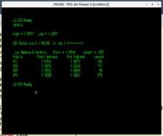
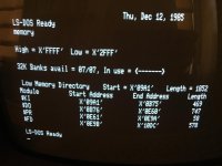
I have run LS-DOS on MAME with -ramsize 512K passed on the command line, and it can use up to 8 32K banks plus the lower 32K (256K+32K=292K), 8 banks show up:
20180406-ls-dos-banks.jpg

To go past 8 banks means rewriting @BANK; my own 320K bank modification for the Model 4 included mods to @BANK for more than eight banks (32, as I recall), since otherwise I would lose 32K of the total 320K. My @BANK replacement source code and doc for the 320K memory mod for the Model 4 is attached; you'd need to massage it a bit to work in the Model II LS-DOS framework, since some of the hardcoded addresses are guaranteed to be different. The @BANK calling conventions are the same for the Model 2 and the Model 4, so with a little work my XBANK code should handle bank switching on port 0FFH easily enough, with up to 32 banks, depending upon how many bits are available in port 0FFH to support that.

The 8-bank LS-DOS @BANK limit is imposed by the bitmaps known as BUR and BAR. BUR (Bank Used RAM) and BAR (Bank Available RAM) need a bit for each bank, and the default LS-DOS 6.3 @BANK only reserves a single byte for each. I needed a ninth bit for the 320K mod, so I aimed high and used 32 bits for BUR and BAR in my @XBANK driver.

EDIT: As far as what good this is, in my case I booted from hard disk on the Model 4 using the XDROM from MADsoft (I don't have that anymore, or I would dump that ROM and reverse engineer a few things), and used a utility called FDR6AT/CMD to do a fast restore from a binary image file to the RAMdisk. This RAMdisk was set up as a system drive, with all of the OS overlays. I used bank numbers 3 through 8 (later I used 3 through 9) for the RAMdisk, which gave a 192K RAMdisk plus a full 128K model 4 underneath. Once FDR6AT was done pulling the disk image from hard disk into RAMdisk, switching drive :0 to the RAMdisk really speeded up the system.
 

Attachments

  • xbank12.zip
    8.2 KB · Views: 4
Last edited:
You guys are making we want to play with extra memory cards this weekend :)
 
I love this forum. A little discussion here about the Model II from you guys spurs me to get off my butt and play with my gear!

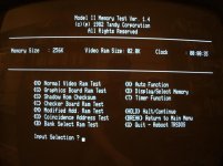
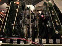
I went ahead and installed four 64K RAM boards in the Model II in my office. This machine has a modern PSU so it can easily run a full card cage. I tried using five memory boards, but the #6 slot on the card cage in this Model II has a short so it's not useable. I adjusted the jumpers and voila...a 256K Model II.

IMG_2890.jpgIMG_2891.jpg

Here's an interesting finding from my testing. It appears that the memory bank jumper settings on page 77 of the Model II Technical Reference Manual are incorrect. This was determined by using the Model II Memory Test program. The Tandy Notes and Jumpers also shows the corrected settings for Banks 0 and 1. The Aton CP/M 2.2 Reference Manual also shows the corrected jumper settings on page 6.

Here are the correct settings:

Bank Jumper

0 J26-J27
1 J25-J28
2 J24-J29
3 J23-J30
4 J30-J22
5 J29-J21
6 J28-J20
7 J27-J19

Now, to think about what to do with all of this Z80 memory.

Thoughts?

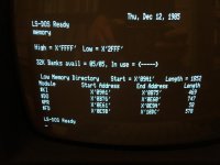
LS-DOS 6.1.3 shows five 32K banks available. I would expect a few more given the machine has 256K. @lowen, any thoughts?

IMG_2892.jpg
 
Last edited:
Pete, looks like a 512K board is going to create a lot of room in your cage.
And without any jumpers.
However, you will need to disable the 16K memory of the HD controller board (when present) as that is mapped into bank 15 (and 14).
2K Video memory mapping is controlled by bit 7 on port FF and is taken into account.
As far as I have found (so far) these two are the only other memory using locations to take care of.

Bank (1~15) selection is controlled by bits 0~3 of port FF by setting them on 0001 to 1111.
When setting the bank selection nibble to 0 (0000), I decided to translate that into 0001. Reason being that also a reset will select bank 0, which (in my opinion) should result in the first 64K of the 512K becoming available to the CPU. I makes no sense in mirroring the first 32K of ram in lower and upper address space after a reset.

On port FF all bits are asigned, otherwise I might consider using bit 4 for making selecting banks 16 ~ 31 possible on a second 512K board.
Bit 4 is used for 40/80 char mode.
Does anybody know of software for the Model 2 that uses 40 character mode?
It also would require software effort to support this second card that would bring total memory in the Model 2 to 1 Megabyte, as this was not part of the design of the machine.
 
I love this forum. A little discussion here about the Model II from you guys spurs me to get off my butt and play with my gear!
...
LS-DOS 6.1.3 shows five 32K banks available. I would expect a few more given the machine has 256K. @lowen, any thoughts?

Nice! Always glad to help people get more interested....

Alright, let's first get a couple of pieces of terminology consistent: in the Model II hardware architecture, a 'page' is 32K and a 'bank' is 64K. The lower four bits of port 0FFH select the page number for all pages except page 0, which is always resident at addresses 0000H - 7FFFH (pages 1 through 15 are switched into addresses 8000H - 0FFFFH, in other words). The 32K/64K memory boards have jumpers for both banks and pages. The LS-DOS 6 term 'bank' is actually the Model II 'page' instead. A bit confusing at first.

I would expect LS-DOS to see seven 'banks' with 256K (the eighth 'page,' 'page' 0, is not counted as an LS-DOS 'bank' since it's always resident). (EDIT: Verified with MAME with -ramsize 256k; memory lists banks available as 07, banks 0 through 6. The Model II 'page' 0 does not count as a 'bank' for LS-DOS). The Model II's architecture is actually a good fit for LS-DOS 6.

Ok, so this post is going to be long, but this needs to be documented in one place, and right now it's scattered all over the place in the LS-DOS sources. Frank was supposed to send me the 6.3.0 Model II code, but never did. My gut feel is that 6.3.0's code was never updated for Model II, and thus there was no 6.3.0 for Model II for Frank to have or to send. Roy did the 6.3.1 for Model II, and that code is probably long gone; I don't know who got Roy's Misosys archives, but I think Bill D. might have gotten some of what Kim Watt had. I was going to attach a ZIP file of the LS-DOS 6.2 sources that I have here that included the BETA version of the Model II (and Model 4, for that matter) code, but the forum's limit is way too small for the zip I have, so here's a link to download.

Looking through the sources, it appears that the code simply walks the banks (LS-DOS term; Model II 'pages') starting at 1 and goes up until the bank doesn't respond as a full 32K bank. Do you have any 16K cards in the system? (ARCnet, hard disk interface are two possibilities)? I would suspect a 16K card or a hole at page 6 (the first page on the fourth board). EDIT: Yeah, I know that's confusing a bit, but Model II page 5 corresponds to LS-DOS 'bank' 4, and that's the last recognized LS-DOS bank. I had to triple check that myself as it was a bit counter-intuitive, and I kept wanting it to be page 7 and not 6.....

Below are extracts from the LS-DOS 6.2.0 BETA sources to document this. Aaron Brockbank also has all of this information and has probably documented what's actually in 6.3.1 better than this 6.2.0ac BETA code.

First, the bank detection code (in SYSINIT2/ASM):
Code:
;
;	determine number of memory banks available
;
	LD	BC,8<8+0	;B=bank, C=bit mask
DETMEM	CALL	TBANK		;test bank D
	RL	C		;move bit into C
	DJNZ	DETMEM		;contine for 8 banks
And the routine TBANK (also in SYSINIT2/ASM):
Code:
;
;	sel mem bank at B and return Cy if not avail
;
TBANK	LD	A,(MODOUT$)	;get flag
	AND	0F0H		;drop low 4 bits
	OR	B		;combine with bank
	CALL	SET_MOD		;update mask/port
	LD	HL,8000H	;start of bank memory
	CALL	TMEM		;test memory here
	SCF			;carry = not avail
	RET	NZ		;go if no memory
	LD	H,0C0H		;next 16k
	CALL	TMEM		;test memory
	SCF			;carry = not avail
	RET	NZ		;go if no memory
	OR	A		;else clear carry
	RET			;done
;
TMEM	LD	A,(HL)		;read data
	CPL			;reverse bits
	LD	(HL),A		;load data
	CP	(HL)		;still there?
	CPL			;reverse back
	LD	(HL),A		;restore data
	RET			;Z=yes, NZ=no memory
;

MODOUT$ and the SET_MOD routine do the actual output to port 0FFH (the code has to keep a mirror of this port value, since you cannot read the currently selected page from the hardware, since it is a 'distributed' write-only port). First, MODOUT$ (from SYSRES2/ASM):
Code:
;*=*=*
;	MODOUT$ mask assignments:
;
;	0-4 = bank number
;	5   = video blank
;	6   = RTC enable
;	7   = video enable
;*=*=*
	IF	@INTL
MODOUT$	DB	21H		;MODOUT international
	ELSE
MODOUT$	DB	21H		;MODOUT port image (FAST)
	ENDIF
;
Note how this is not correct: only data bits 0-3 are 'page' selects (15 pages available; page 0 isn't switchable), as bit 4 is documented as being the 80/40 character mode switch.

and now SET_MOD (from CLOCKS2/ASM)
Code:
SET_MOD	LD	(MODOUT$),A	;update image
	OUT	($BSEL),A	;re-set
	RET			;done

$BSEL is (from BOOT2/ASM):
Code:
$BSEL	EQU	0FFH		;bank/video select port

Ok, the operating @BANK SVC code (from CLOCKS2/ASM):
Code:
@BANK
	PUSH	HL		;save HL
	LD	A,B		;get command
	LD	HL,BANKTBL	;lookup table
	CALL	@LOOKUP		;search entry
	EX	(SP),HL		;get HL, leave vector
	RET	Z		;go vector if found
	POP	AF		;remove vector
	JP	PERR		;go param error!
;
BANKTBL	DB	0		;select bank
	DW	BANK0
	DB	1		;unmark bank
	DW	BANK1
	DB	2		;test bank
	DW	BANK2
	DB	3		;mark bank
	DW	BANK3
	DB	4		;select bank
	DW	BANK4
	DB	-1		;terminator
;
BANK4	LD	A,(LBANK$)	;P/u current bank
	CP	A
	RET
;
;	set bank in use
;
BANK3	CALL	BANK2		;valid and available?
	RET	NZ		;nope, go!
	JR	BMARK		;mark and return
;
;	reset bank
;
BANK1	CALL	VALBANK		;valid bank#?
	RET	NZ		;nope, go!
	JR	UMARK		;unmark and return
;
;	test bank in use
;
BANK2	CALL	VALBANK		;valid bank#?
	RET	NZ		;nope, go!
	JR	MTEST		;test bank marked
;
;	select bank
;
BANK0	PUSH	HL		;Ck if stack is in upper
	LD	HL,8005H	;  bank area
	ADD	HL,SP
	POP	HL
	JP	C,PERR		;Error if > X'7FFE'
	CALL	VALBANK		;valid bank?
	RET	NZ		;go if not
	LD	A,(MODOUT$)	;P/u current memory
	AND	0F0H		;remove bank address
	LD	B,A		;save temp
	LD	A,C		;get bank # needed
	AND	7FH		;remove jump bit
	INC	A		;bump to correct bank
	OR	B		;combine
	CALL	SET_MOD		;set new memory image
	LD	A,(LBANK$)	;Get old bank #
	LD	B,A		;  & save it
	LD	A,C		;P/u new bank #
	AND	7FH		;Strip any bit-7
	LD	(LBANK$),A	;  & save new bank #
	XOR	C		;keep bit 7
	OR	B		;merge in new bank
	LD	C,A		;replace for return
	BIT	7,C		;Transfer to new bank?
	LD	B,0		;Init for invoke later
	RET	Z		;No if bit-7 = 0
	EX	(SP),HL		;Exchange RET with new
	CP	A		;  transfer & go to it
	RET
;
VALBANK	LD	A,C		;get bank #
	AND	7FH		;remove jump bit
	CP	8		;0-7?
	JR	C,ATEST		;yes, check if exists
INVBANK	JP	PERR		;param error
;
;	test if bank exists
;
ATEST	PUSH	HL		;save
	LD	HL,BAR$		;bank avail ram
	JR	AMTEST		;continue
;
;	test if bank is marked
;
MTEST	PUSH	HL		;save
	LD	HL,BUR$		;bank used ram
;
AMTEST	PUSH	BC		;save
	CALL	BSETUP		;setup for test
	LD	A,(HL)		;get data
	AND	C		;marked?
	POP	BC		;restore
	POP	HL
	JR	NZ,INVBANK	;go if not
	RET			;else return Z
;
;	set bank # as marked
;
BMARK	CALL	BUSET		;setup
	OR	C		;mark bank
	JR	MUCOMM		;continue
;
;	unmark bank #
;
UMARK	CALL	BUSET		;setup
	AND	B		;unmark!
;
MUCOMM	LD	(HL),A		;update data
	POP	BC		;restore
	POP	HL
	XOR	A		;set NO error
	RET			;done
;
;	setup for bank activity
;
BUSET	POP	AF		;get caller
	PUSH	HL		;save registers
	PUSH	BC
	PUSH	AF		;return back
	LD	HL,BUR$		;bank used ram
	CALL	BSETUP		;setup
	LD	A,(HL)		;get data
	RET			;return with data
;
;	setup for bank activity
;
BSETUP	RES	7,C		;force in range
	INC	C		;init for test
	LD	B,1		;init bit 0
BSETUP1	DEC	C		;found?
	JR	Z,BSETUP2	;go if yes
	SLA	B		;shift test bit
	JR	BSETUP1		;continue
BSETUP2	LD	A,B		;get test bit
	LD	C,A		;C=set bit
	CPL			;reverse bits
	LD	B,A		;B=reset bits
	RET			;done
 
Last edited:
Nice! Always glad to help people get more interested....

I would expect LS-DOS to see seven banks with 256K. (EDIT: Verified with MAME with -ramsize 256k; memory lists banks 0 through 7).

Looking through the sources, it appears that the code simply walks the banks (LS-DOS term; Model II 'pages') starting at 1 and goes up until the bank doesn't respond as a full 32K bank.

This was the issue. I was testing different jumper settings on the fourth memory board. When I had it set to bank 7 (that's Model II Bank #7), the Memory Tester program still recognized it. That's when I booted up LS-DOS. But, as you describe, LS-DOS stops looking if there is a gap in the bank usage. So LS-DOS only saw 3 memory boards. I switched the fourth card to MII bank 3 and now I have 7 LS-DOS banks.

IMG_2893.jpg
 
This was the issue. I was testing different jumper settings on the fourth memory board. When I had it set to bank 7 (that's Model II Bank #7), the Memory Tester program still recognized it. That's when I booted up LS-DOS. But, as you describe, LS-DOS stops looking if there is a gap in the bank usage. So LS-DOS only saw 3 memory boards. I switched the fourth card to MII bank 3 and now I have 7 LS-DOS banks.

Excellent!

So this new 512K card would need to have a resident, fixed, page 0, then allow switching of pages 1 through 15.

The basic logic is actually deceptively simple: latch port 0FFH. Make sure the video RAM bit is supported, by the way, with the logic like on the 32K/64K board (the OP mentioned this in the first post). Take the lower four bits of the 0FFH latch, feed one side of a four-bit mux with those four bits and the other side of the mux with zeroes. Remember the bus logic on the Model II is a bit odd, but take the positive-logic A15 as the select line of the four bit mux. The output side of the four bit mux goes to A15, A16, A17, and A18 of the 512Kx8 RAM chip. If A15 is zero, mux in zeroes; if A15 is one, mux in the page nybble.
 
Last edited:
Excellent!

So this new 512K card would need to have a resident, fixed, page 0, then allow switching of pages 1 through 15.

The basic logic is actually deceptively simple: latch port 0FFH. Make sure the video RAM bit is supported, by the way, with the logic like on the 32K/64K board (the OP mentioned this in the first post). Take the lower four bits of the 0FFH latch, feed one side of a four-bit mux with those four bits and the other side of the mux with zeroes. Remember the bus logic on the Model II is a bit odd, but take the positive-logic A15 as the select line of the four bit mux. The output side of the four bit mux goes to A15, A16, A17, and A18 of the 512Kx8 RAM chip. If A15 is zero, mux in zeroes; if A15 is one, mux in the page nybble.

I forgot about this discussion. I was going to add that there's a TRSDOS mode and a CP/M mode, at least with the 12/16B/6000. There's details in the Model 6000 tech manual Pete recently put in the archive. In CP/M mode page 0 can be swapped out. This is a requirement for the banked CP/M Plus. Aton probably uses this mode as well.
 
Last edited:
I forgot about this discussion. I was going to add that there's a TRSDOS mode and a CP/M mode, at least with the 12/16B/6000. There's details in the Model 6000 tech manual Pete recently put in the archive. In CP/M mode page 0 can be swapped out. This is a requirement for the banked CP/M Plus. Aton probably uses this mode as well.

Interesting. Can you provide a reference to the document and page #? I’ve uploaded so many documents recently I’m not sure to which one you are referring. :) Thanks!
 
Interesting. Can you provide a reference to the document and page #? I’ve uploaded so many documents recently I’m not sure to which one you are referring. :) Thanks!

Tandy 6000 Service Manual, starting at page 139.

At some point I'm going to see about recreating the PAL that allows 128K on the system board (unless someone already has that PAL and can read it).
 
Back
Top