• Please review our updated Terms and Rules here

Sick 5150 16K-64K No Post, just burps

KLund1

Veteran Member
Joined
Jun 22, 2012
Messages
561
Location
Livermore, CA
Hello again everyone.
I now have a 5150 16K-64K motherboard that will not post. The MB shows no physical damage. It was not dusty when I got it. It has a 10/19/81 BIOS IC, and Cassette basics ver 1.00 ROMS.
When connected to known good PSU, no cards, and just the speaker, when power is applied the speaker make a burp buzz sound for a 2 seconds. NO beep(s). The the PSU fan stops spinning too. SW1 was all on except 5 & 6. I then looked a lot closer at the yellow caps. All looked to be in good condition, but that dose mean thy are good. While looking at the caps, I noticed the a lot of the socketed RAM was inserted backwards. I put them all back correctly, reseated everything else, and powered up. I got the same sounds. I them pulled all the RAM out and put SW2 to all on (16K). Power on still gave the same sound. Could the ram being in backwards have damaged something? RAM in U69 & U85 were also in backwards.
I do not have a scope, nor how to use one. Just a multimeter and a soldering iron.
I do have a non-working 64K-256K 5150 board with the later BIOS, and 2 dead XT boards (will get to those later...)
What would be the next step in testing that I could do?
 
I'd be looking at replacing all the ram that was in backwards, It's pretty much a certainty they are all fried now, Tantalum's can look brand new and be shorted / dead inside, lots of information on Modem7's Site.
 
Thanks,
Any danger that the 16K that is soldered onto the MB is bad because of the socketed ram being in backwards?
I'll start desoldering T-caps and testing them. I'll start with the ones closest to the power connection and work out from there.
What would be a good value for replacements?
 
Before you go getting out the soldering iron, Make sure you have had a good read through Modem7's site, A good place to start is Here, Do not start pulling caps until you've read and understand what caps to look for on the 16 - 64 motherboard. it's possible there may be a bad ram in the first 16k. Tants are 16v 10uf or i have used 25v 10uf before.
 
Thanks everyone.
Yes that is the first place I went to start diagnostics on this board. From there I know what caps to pull and check. It looks like the -5v side where the memory is.
I did not see a page that talks about the soldering in memory. How do I check that?
Update - I found the section that shows how to check the first 16K with the pipgyback method. Though not 100% accurate, but a good start.
 
Last edited:
So it seems to stay powered for 2 seconds before the power supply shuts down?

That is a little odd. Usually a shorted capacitor will cause a power supply to shut down almost immediately. Does anything get warm on the motherboard? (Don't get too close to the board while force feeding it power - bad tantalums can go boom in your face).

16k RAM chips use 5v, -5v, and 12v instead of just 5v. Putting one in backwards will usually kill it. And during failure odd voltages could escape on to the bus. While it may have damaged the other RAM chips, there is a good likelihood it damaged other components as well, and of course there may have been other damage already if someone was just using it to hold chips. (But socketing the first 16k would save headache in the long run anyway)

Once you get it to a point where the power supply does not shut down, and if it still does not operate, then you should try the Supersoft ROM diagnostic. (Also on Modem7's site)
 
I agree 2 seconds is a little long. Nothing else gets warm. But that buzz burp sound has me thinking possible the BIOS Rom might be bad?
I did the piggyback thing with each soldered RAM one at a time. Nothing. I piggybacked all the ram. still no change. So I started pulling T-caps. I did find a shorted cap at the C6 closest to the white power connector. The other C6 closest to the cassette port reads 11.61uf. Other C7's by U36, U99 read 10.51uf The C7 by U93 read 11.59uf. That is as far as I have tested. The only T-cap I have on hand is a 25v 10uf. Can I use that for the shorted cap? Or safer to wait until I get some 16v 10uf's?

As far a using Supersoft ROM? I do not know how to burn a rom. never done it before. I do have a burner like this
https://www.ebay.com/itm/New-USB-TL...190651&hash=item3f7e565934:g:nYgAAOSw3upa1w4T
I do have some epoms but the are D2716's but the supersoft page dose not list this as compatible.
 
Great. I solder it in. Powered it up
IT LIVES !!!
Connected a Mono card and mono screen and it boots to basic!!
Many Thanks everyone!!!!!
I'll add memory IC's then cards, tested each along the way.
 
I did find a shorted cap at the C6 closest to the white power connector.
I have added that failure to [here].

As far a using Supersoft ROM? I do not know how to burn a rom. never done it before. I do have a burner like this
https://www.ebay.com/itm/New-USB-TL...190651&hash=item3f7e565934:g:nYgAAOSw3upa1w4T
I do have some epoms but the are D2716's but the supersoft page dose not list this as compatible.
Because a 2716 holds 2 KB, and the PC/XT version of the diagnostics is 8 KB sized.

The people at [here] can burn a 27xxx series EPROM for you, if desired. But maybe now is a good time for you to learn how to burn your own.

Note that a 27xxx series EPROM needs an adapter if it is to be used on a 5150 motherboard.

Just to check, with all ram banks filled, I get 61404 byte free. No errors on screen. This correct?
Looks right. That will be the 64 KB on the motherboard, minus whatever DOS is using.

You will see something similar if you boot to Cassette BASIC; 64 KB minus whatever is used by BASIC. However, later, if you increase conventional RAM past 64 KB, be aware that the "Bytes free" figure presented at startup of Cassette BASIC will not change.
 
Ok I'm good up the point where I connect 2 floppy single sided 360K drives. With one drive SW1 settings, it boots to dos fine. When I add the second drive, change SW1 for 2 drives, and boot, they both drive light up and spin. Then it drops to Basic. The FD card is the very early version here
http://minuszerodegrees.net/5150/early/5150_compare_diskette_adapter.htm
The jumpers at the top left are NOT shorted on the card.
The cable appears to be correct. It it twisted on one side. The cable ends has that little notch so it can only slide on the edge connectors only one way.
I have switched the drives, no change. I think I am missing something simple. I do not think there are jumpers on these early drives?
See picture for some details.
 

Attachments

  • DSCN1897[1].jpg
    DSCN1897[1].jpg
    99.1 KB · Views: 1
Ok I'm good up the point where I connect 2 floppy single sided 360K drives. With one drive SW1 settings, it boots to dos fine. When I add the second drive, change SW1 for 2 drives, and boot, they both drive light up and spin. Then it drops to Basic.
I suggest that you first try one drive at a time as A: (drive at end of cable, second drive-select option, terminator fitted).

That way, when trying for a dual-drive configuration, you know that both of the drives are ruled out as a problem source (unless you forget about termination rules).

(And I presume that you are aware of the diagram at [here].)

I do not think there are jumpers on these early drives?
The manuals for the drives will be online, and they will reveal how drive-select is done on that particular model of drive. For example, common on the Tandon TM200 is the use of a wire jumper, per the top-left corner of the following photo.

tandon_tm100-2_terminator_1.jpg
 
Ok I'm good up the point where I connect 2 floppy single sided 360K drives. With one drive SW1 settings, it boots to dos fine. When I add the second drive, change SW1 for 2 drives, and boot, they both drive light up and spin...The cable appears to be correct. It it twisted on one side.
Both the HD cable and the floppy cable are twisted on one side -- but they are twisted on different sides so it's important to note which side has the twist. If you're using the wrong cable it won't work. And, which position on the cable is the single drive connected to when it works?
 
Thanks,
I had forgotten about the terminator. Is the terminator an IC, or the little wire?
I am fairly sure I have a floppy cable, not a HD cable, but I have attach a pic. Could you verify.
Neither drive has a model number on it any where. I have tried many combinations of cable connections and that little terminator wire in and out the empty socket. The other drive has a thing in it that shorts many pins. Both drives work as A.
Could you look closely at the pic in post 12, and kindly direct what changes need to be made. I would prefer the drive on the right to be A.
 

Attachments

  • DSCN1898[1].jpg
    DSCN1898[1].jpg
    98.2 KB · Views: 1
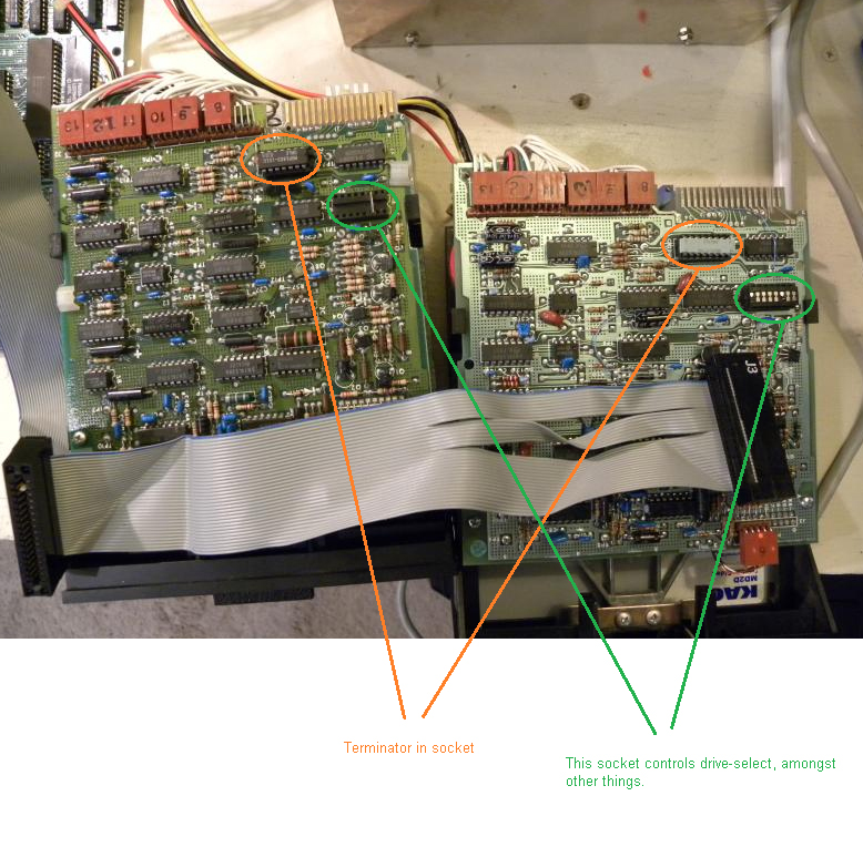
See photo below.

I can see that the drive-select options in both drives is correct (expected because you were able to get each drive working on its own.)

In a dual-drive configuration, there must only be one terminator, ideally in whatever drive is the end of the cable.


temp_117439053.jpg
 
Neither drive has a model number on it any where.
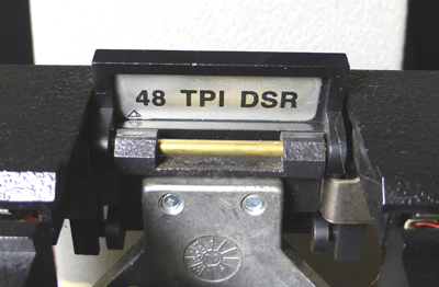
Those drives look like Tandon ones, and the Tandon drives that I own are double sided, and have the model number printed on a silver coloured label on the bottom side of the drive. Some of the labels are small.

On mine, there is a tracks-per-inch (TPI) figure underneath the front panel latch. 48 TPI is what is required for the IBM 5150.

tm100_tpi_sticker.jpg


The "DSR" possibly stands for "double sided recording".
 
Those jumpers don't look quite right to me, but the photo is a bit blurry.

From the right to the left (in the photos shown above) the jumpers pins ("programmable shunt socket" as the manual calls it) should be:
- HS/Not used
- DS0
- DS1
- DS2
- DS3
- DS4
- MX
- Spare
- HM/Not used

In an IBM PC twisted cable configuration the only connection should be DS1, the third set of holes (or switch) from the right. As shown in Modem 7's earlier picture, but that photo is left to right. (post #13)

It looks like one drive just has a wire jumper. But the other looks like it has a punch-out jumper pack? (Some drives can have DIP switch packs installed there instead). And it looks like DS2 and DS3 are jumped?

Any rate, having multiple DS lines jumped can cause A: and B: to activate at the same time. Try removing that jumper pack and installing a wire as shown in Modem 7s earlier photo.

Edit: I mean shunt pack, not jumper pack. Brain no werky.
 
Last edited:
Ok I think I got it.
In a 1 or 2 drive PC/XT, the third from the right should always be shorted. And that terminator IC should be removed for the first drive after the card on the cable in a 2 drive system. Leave it in for a one FD system.
Done and it WORKS!! Both and A & B are accessible!!
Again many thanks for the hand holding!! Very much appreciated!!
The system now appears to be 100% functional. At least outside the case. Time for a screwdriver.....
 
Back
Top